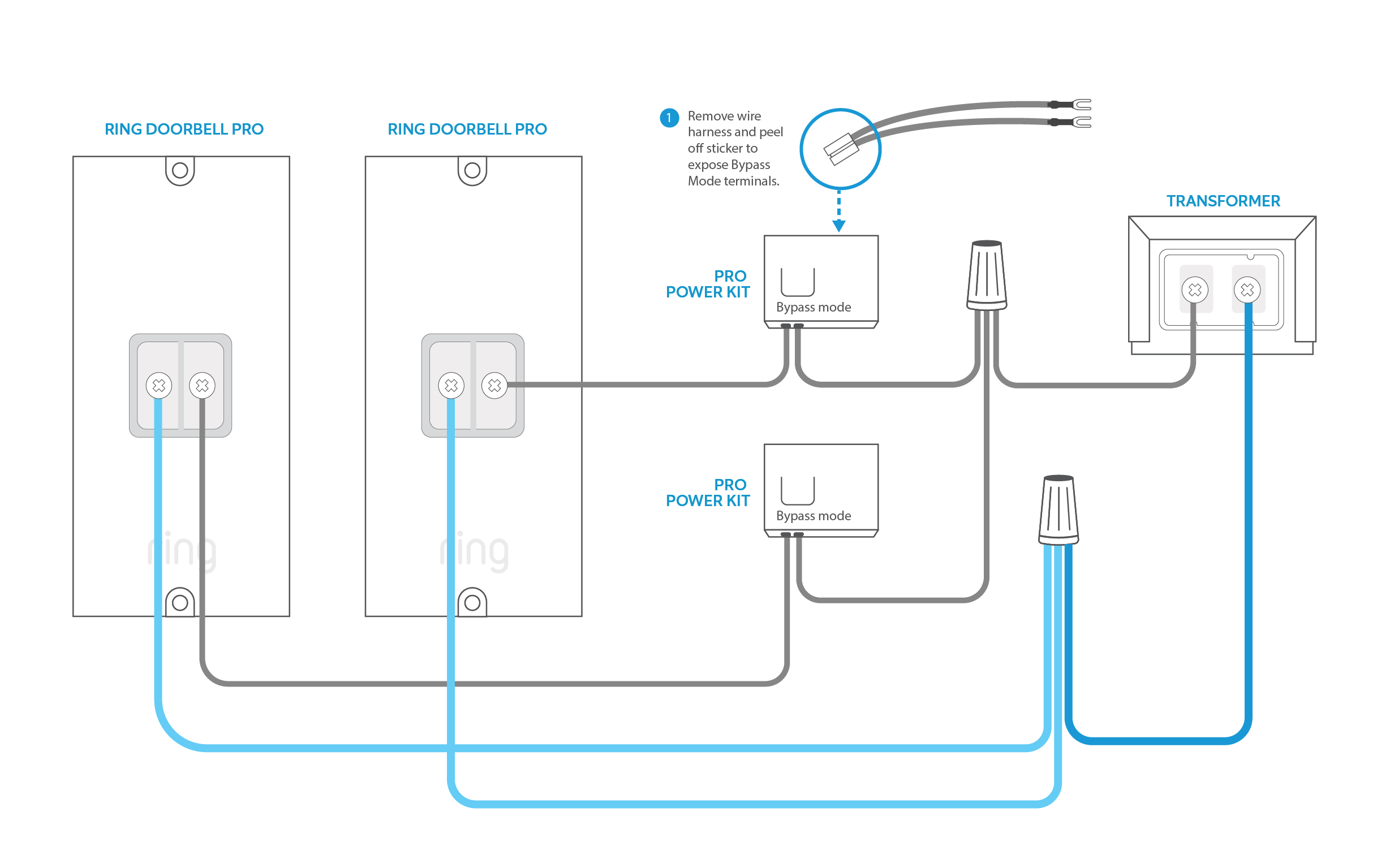
It is this simplicity that makes doorbell such a marvel. Connect the input wires on the transformer to the source circuit using the black to black white to white and ground to green method.

Sb 1996 Electronic Doorbell Light Circuit Schematic
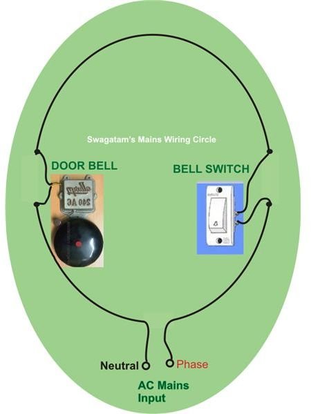
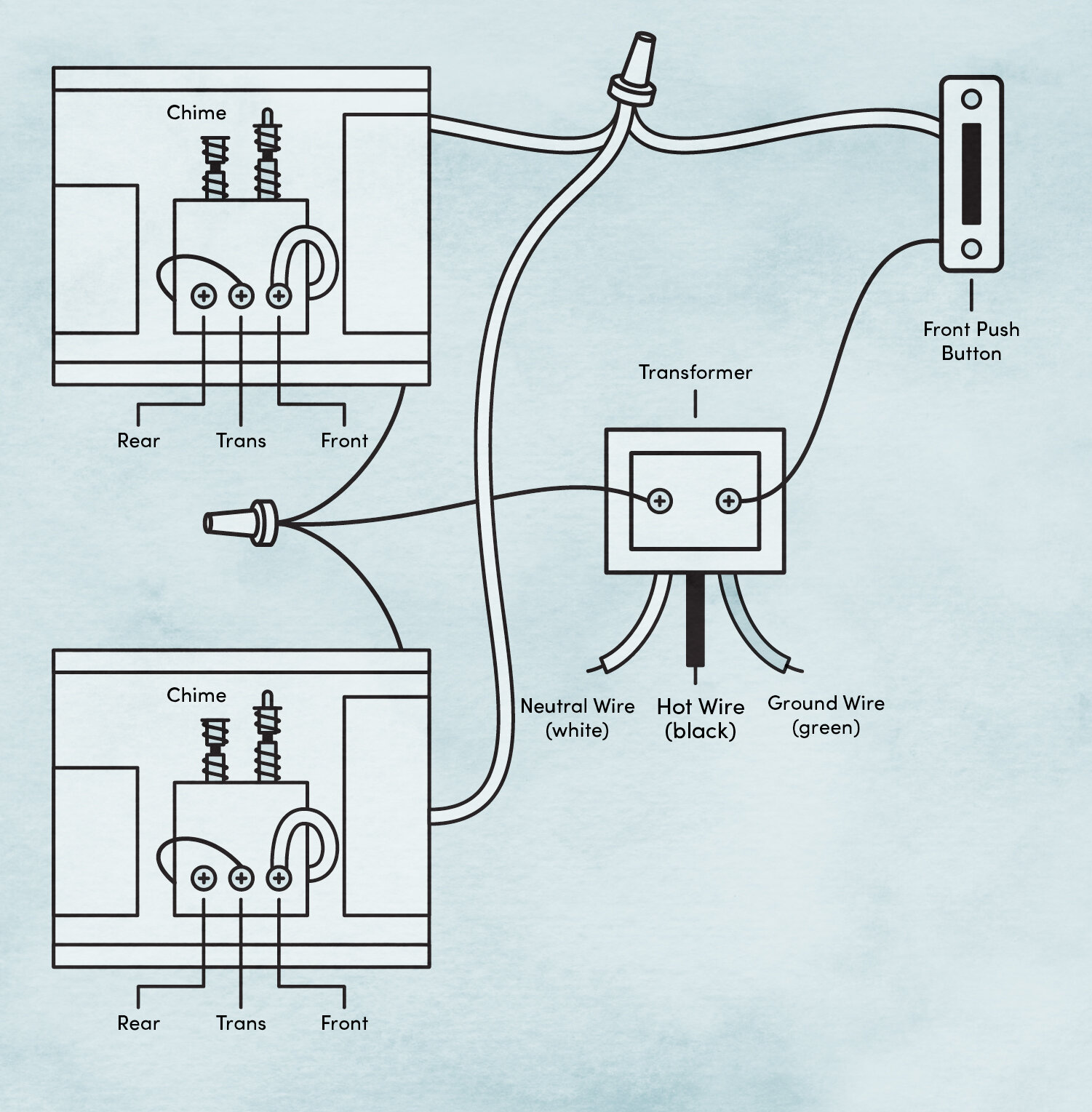
Electric bell wiring diagram. Doorbells are typically wired with 18 gauge wire also referred to as bell wire. Wiring diagram for a two chime doorbell wiring for two doors is the same as for one with the transformer hardwired to the 120 volt source from a house circuit. The low voltage side will usually have a couple of screw terminals to connect your 18 gauge bell wire to. In electrical wiring doorbell wiring is very important and useful connection. If you try to press switch s2 a second time when the first ding dong sound is still being produed it has no effect whatever and the two ding dong bell sounds will be invariably produced. Terminals on the buzzerbell are commonly labeled f r and c.
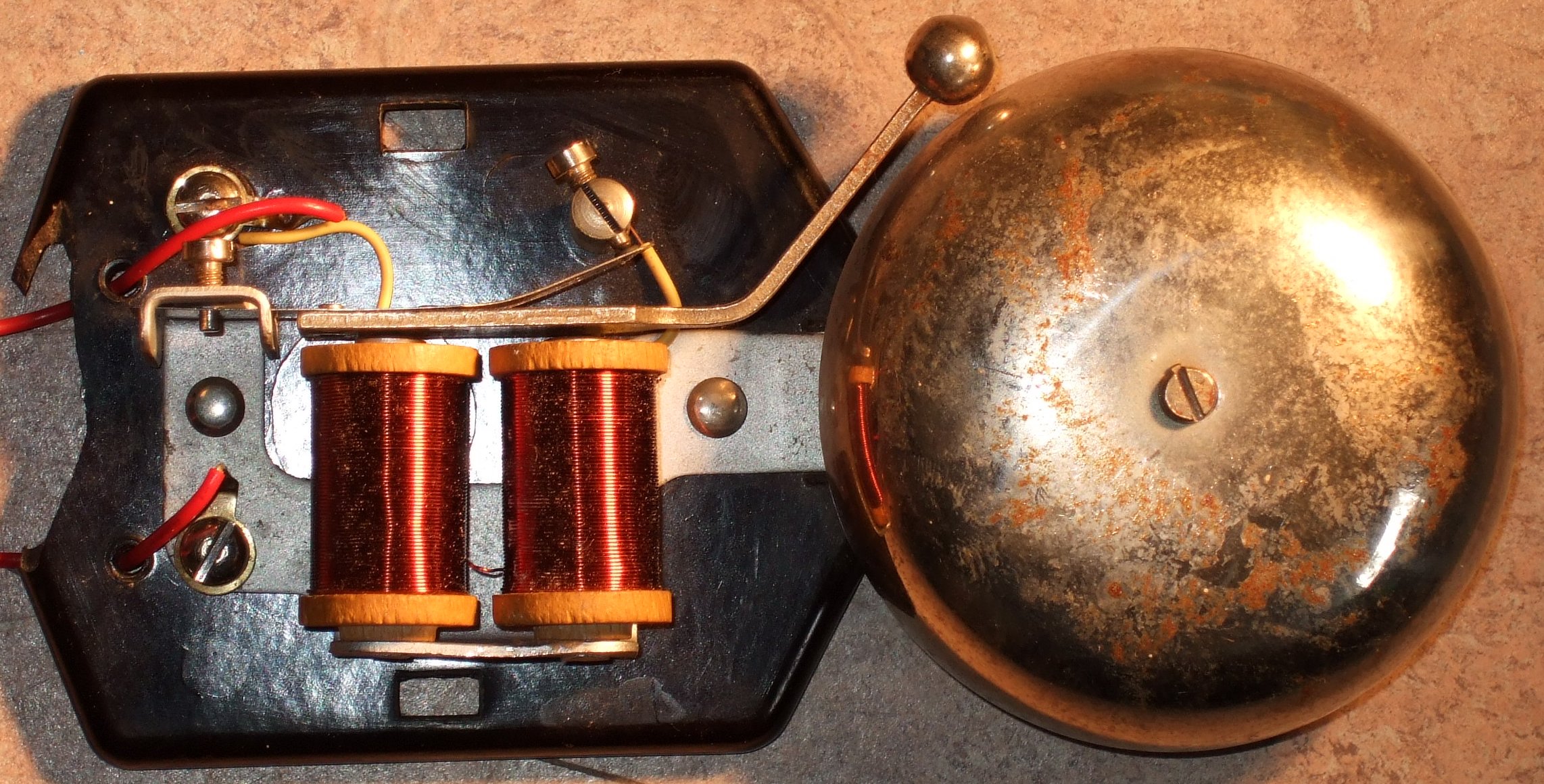
The door bell shown in the diagram can be replaced by either a fan light or any other appliance to get the particular relevant wiring completed. In every home we wire a doorbell and with out this wiring connection the all wiring is incomplete. You can see that a door bell normally has two wires which needs mains supply voltage to operate the bell switch also has two terminals and functions as a cut off system and stops the flow of. Doorbell electronic circuit diagram. Each time switch s2 is pressed ding dong sound is produced twice. The simple devices in the doorbell put the scientific principle of electromagnetism into action in a useful way.
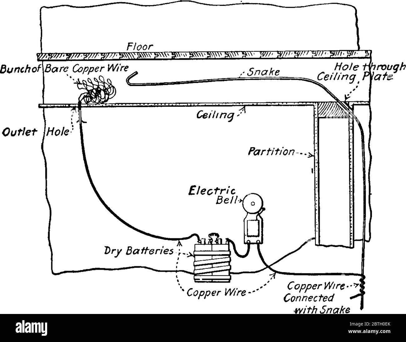
The electric doorbell is a simple circuit that triggers a sound on the completion of circuit by pressing the button. In this post i will share three wiring diagrams of door bell in which i shown door bell transformer wiring door bell with push button and two door system wiring. Therefore switch s1 may be kept closed.
Gallery of Electric Bell Wiring Diagram