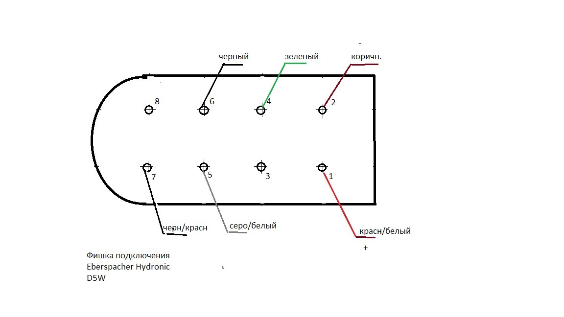
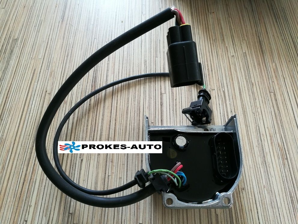
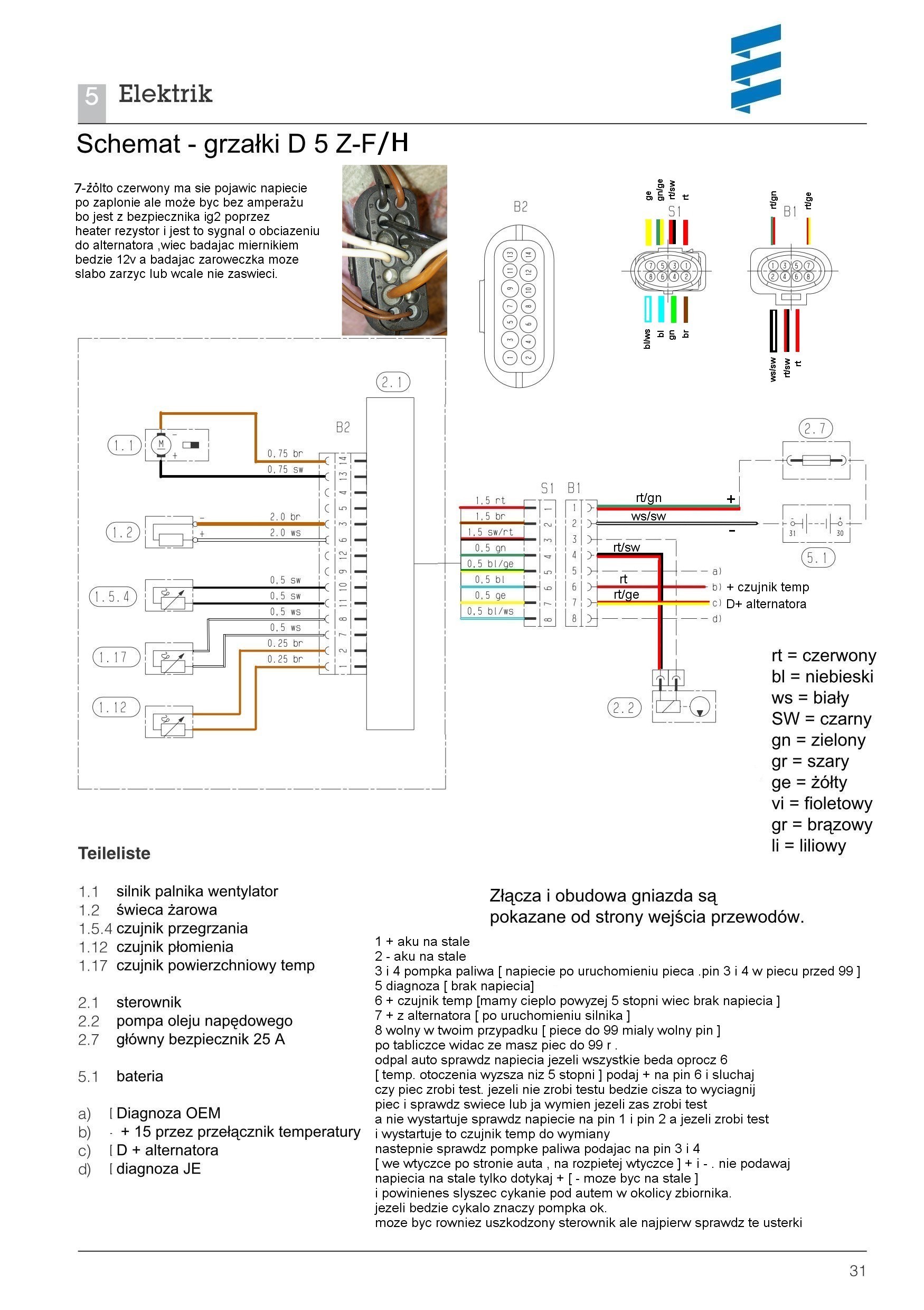
Eberspächer gmbh co. Glow plug overheating sensor 112 flame sensor cable colours 113 temperature sensor rt red control unit bl blue dosing pump.
Volvo V40 D2 User Wiring Diagram Diagram Base Website Wiring
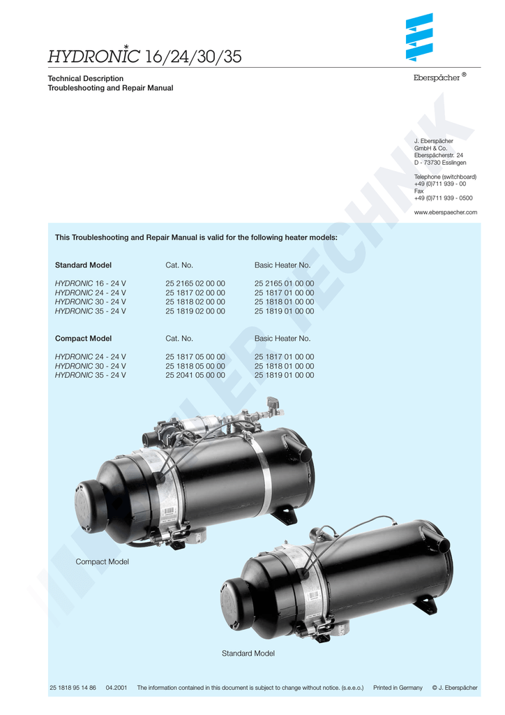
Eberspacher d5wz wiring diagram. Wiring diagram helpful wiring information when hard wiring your brake control. Eberspacher d5wz wiring diagram 20102018 20102018 1 comments on eberspacher d5wz wiring diagram here youll find a range of literature to aid in maintaining your hydronic d5wz. Run two wires to the battery. If no voltage is applied check the supply lead yellow ge 05 mm² wire the 5a fuse item 271 in wiring diagram on pp. This applies in particular to the electric wiring circuit diagrams the fuel supply the combustion air and ex haust gas duct. Whether thats installation technical information eberspacher parts lists.
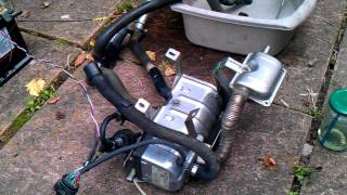
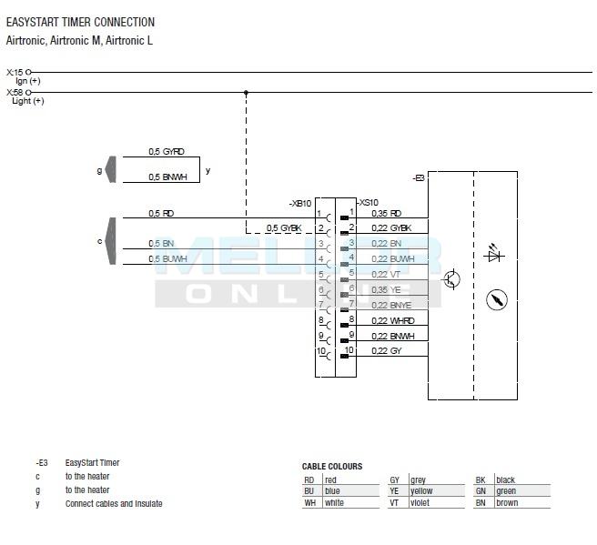
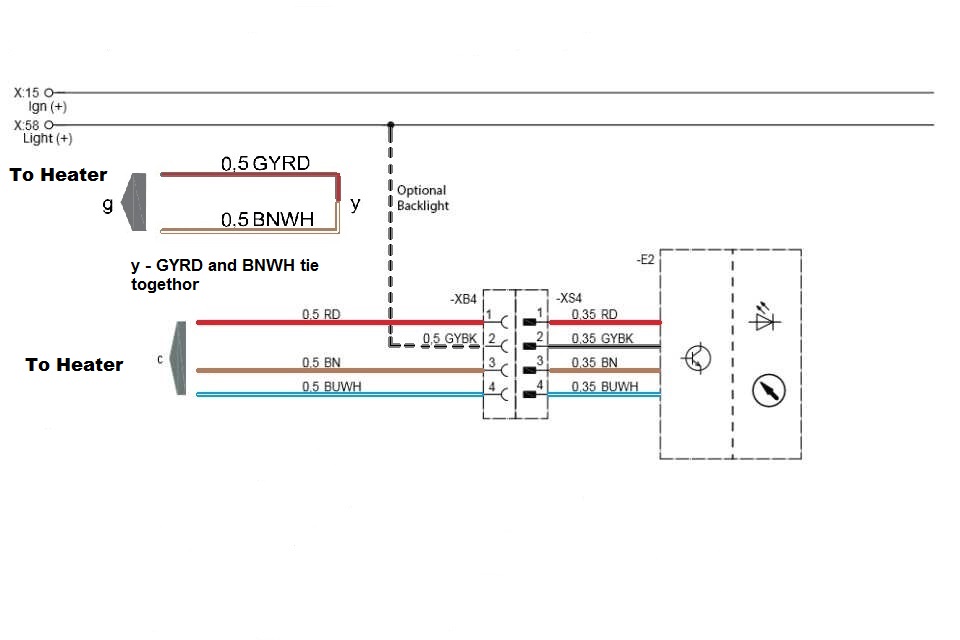
Always wire the red wire to the heaviest gauge wire when testing cold side of brake switch. Circuit diagram electrical system circuit diagram 25 1988 00 96 01 c parts list connectors and bush housings are shown burner motor from the cable inlet side. Circuit diagram airtronic d2 d4 short optional loom circuit diagram airtronic d2 d4 heaters supplied with short optional loom rt 05 ge 05 gr 05 swrt 05 gnrt 10 br 10 br 05 blws 05 grrt 05 brws 05 8 way housing gr 05 br 05 319. Van d5wz bench testing092011 duration. White ground black power blue run to electric brakes at the rear plug red run to cold side of brake switch off of the brake pedal using a test light to find the cold side note. 24 and 25 and the operating element.
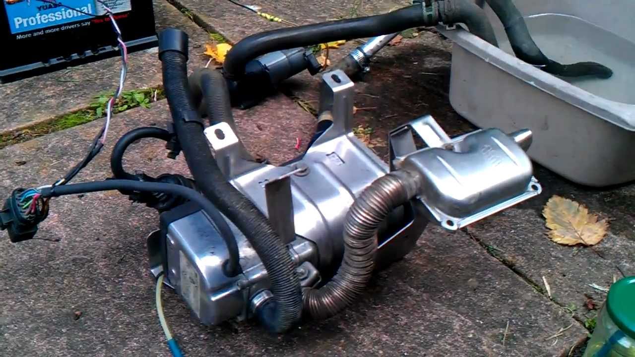
44 1425 480151 fax. 2 diagnostic devices 4 multiple diagnostic devices are available as outlined below. Ensure that the insulation of electrical lines cannot be dam. At intervals of approx. Eberspacher d3wz hydronic wiring diesel water heater 12v boatcampervanready to install x007john. This manual is designed to be used with the hydronic d5 s and sc.
Fuel pipes and exhaust pipes must be safely fastened to avoid damage from vibrations recommendation. Climate house yeoman road ringwood hampshire bh24 3fa phone. Check operating element timer modulemini timer disconnect the plug from the operating element and bridge the red rt 05 mm² wire and the yellow ge 05 mm² wire. Wiring diagram for control switches.
Gallery of Eberspacher D5wz Wiring Diagram