It may in some cases even return to the wall from the second switch. They come in single pole and 3 way.
Wiring Diagrams Double Gang Box Do It Yourself Help Com
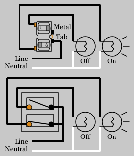
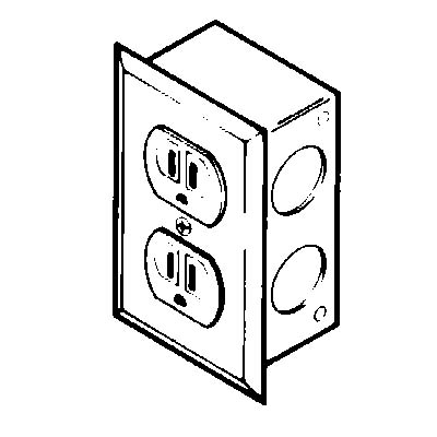
Duplex switch wiring diagram. This wiring diagram illustrates adding wiring for a light switch to control an existing wall outlet. These receptacles are usually found in kitchen wall outlets where two branch circuits are needed to serve small appliances and a refrigerator separately. 1 turn off the circuit breaker that supplies power to the circuits on which you will be working. The source is at the outlet and a switch loop is added to a new switch. Also shown is the half of the receptacle that is live at all times and the tab that must be cut in order to split the receptacles. This tab is removed to isolate the tabs from each other.
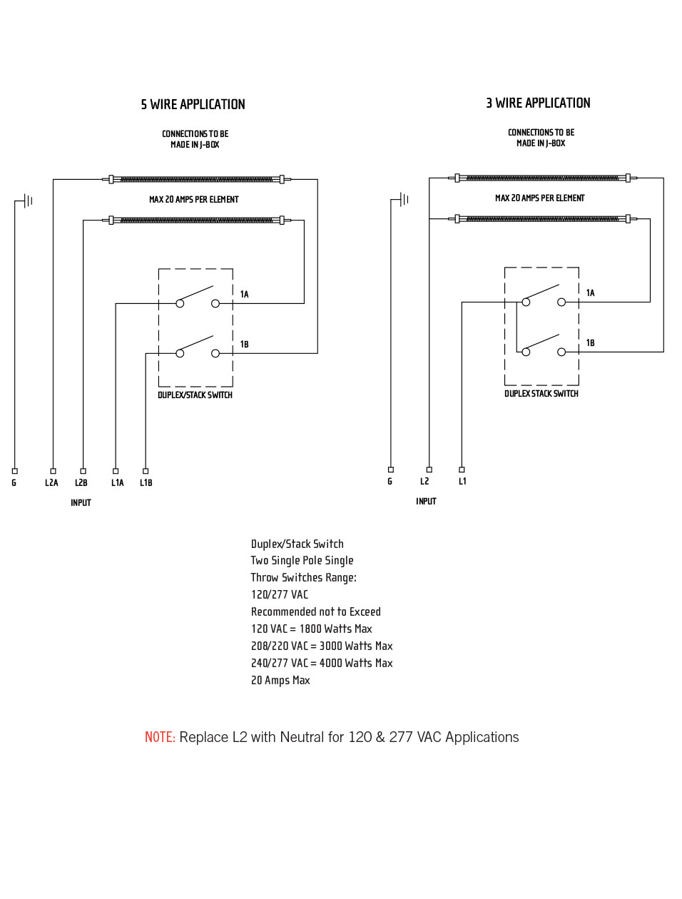
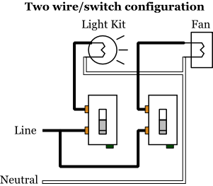
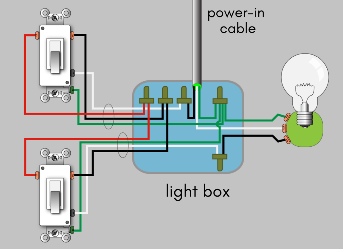
The source is at the sw1 where the hot is connected to. Wiring diagram for a 20 amp 120 volt duplex receptacle a 20 amp 120v duplex receptacle outlet like this should be installed in a circuit using 12 awg cable and a 20 amp circuit breaker. Uinfratechcontrolsduplex switch 85 x 11 1 author. In this diagram two 3 way switches control a wall receptacle outlet that may be used to control a lamp from two entrances to a room. A hot wire red or black comes out of the wall and into one switch then out of that switch and into the other one. The black wire from each light is connected to one of the switches and the source neutral and ground are shared by the two light fixtures.
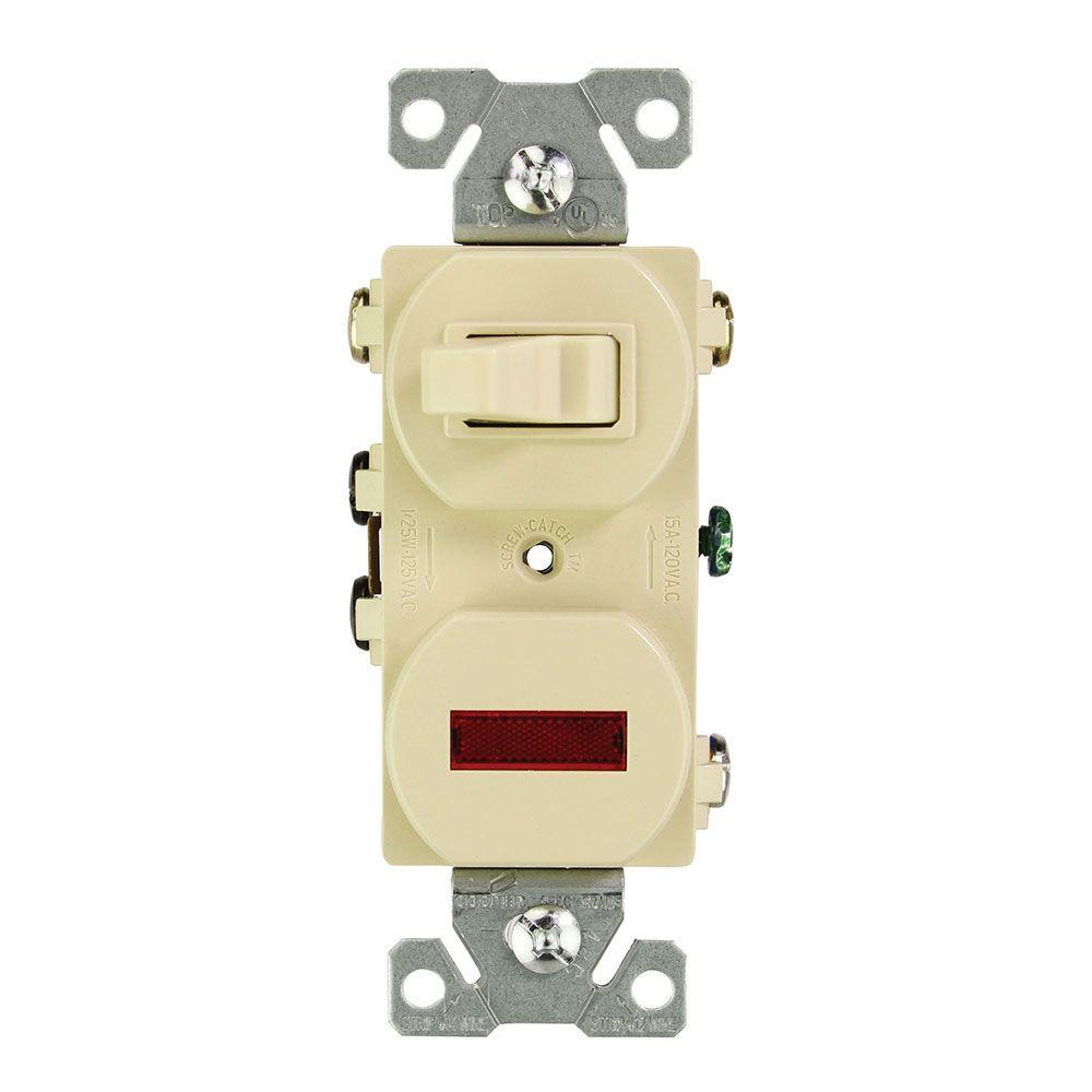
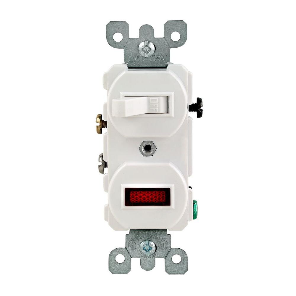
Duplex switches are common in residential wiring because they conserve wire. Heres a wiring method that eliminates extra connections and creates a neater installation. Instead of running a separate pigtail from the hot wire to each switch just leave the hot wire extra long. A duplex switch contains two switches on one body. This diagram shows two switches in the same box with a separate 120 volt source feeding each. To connect the switches simply score the wire with your wire stripper and push the insulation to expose about 34 in.
Three wire cable is supplying the source for the switches and the black and red wires are each connected to one switch. Two of the common terminals are connected together with a removable metal tab. Depicted here is the wiring diagram for controlling the half of two duplex electrical receptacles by a wall switch without a neutral conductor. This circuit is wired the same way as the 3 way lights at this link. The black wire from the switch connects to the hot on the receptacle. These terminals are usually connected to line voltage and can be black or bronze color depending on the manufacturer.
My light switch wiring diagrams may be helpful to you. Dont let this discourage you simply attach the hot wire on the new fixture exactly how you found it on the old wire. Three wire cable runs between the switches and the outlet. 3 way switched outlet wiring. The hot source wire is removed from the receptacle and spliced to the red wire running to the switch.
Gallery of Duplex Switch Wiring Diagram