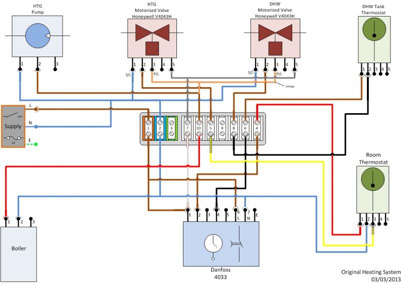
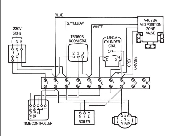
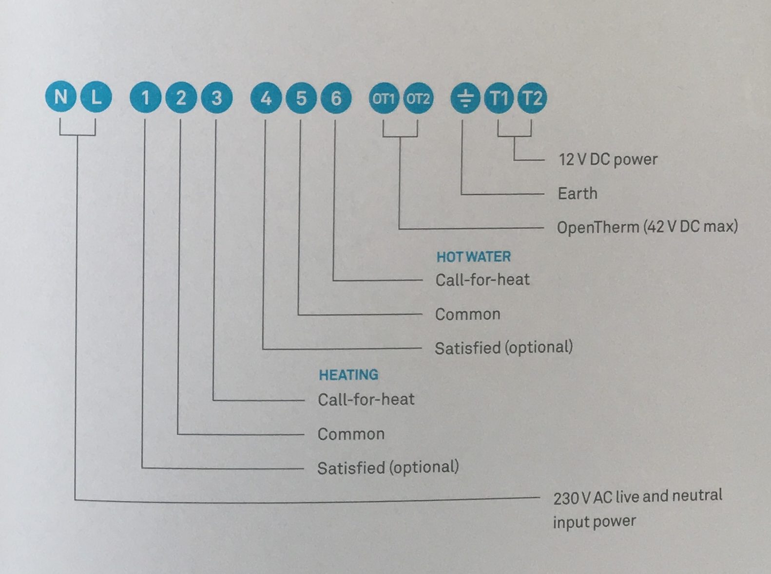
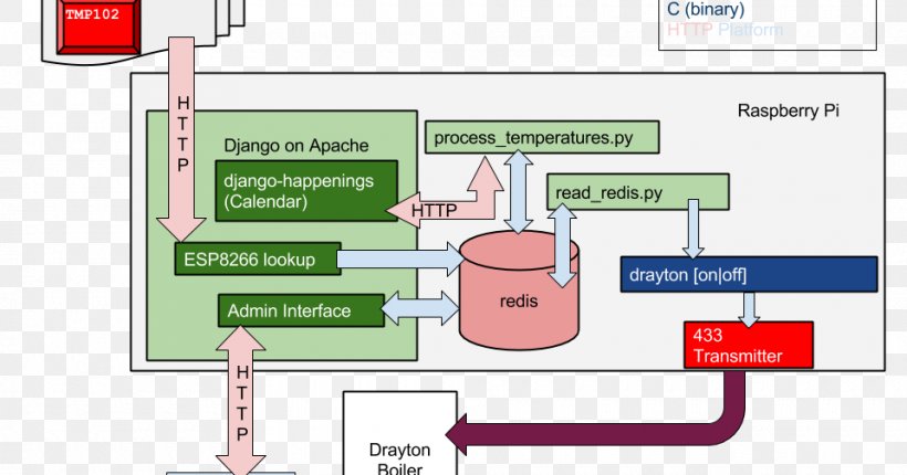
22092 rf700 22090 digistat rf70022090 digistat rf rf70122092. Wiring diagrams probably the highest number of requests draytons technical team receives every week is for help with wiring diagrams using the lwc1 or lwc3 wiring centre.

How To Install The Nest Learning Thermostat 3rd Gen In A Y
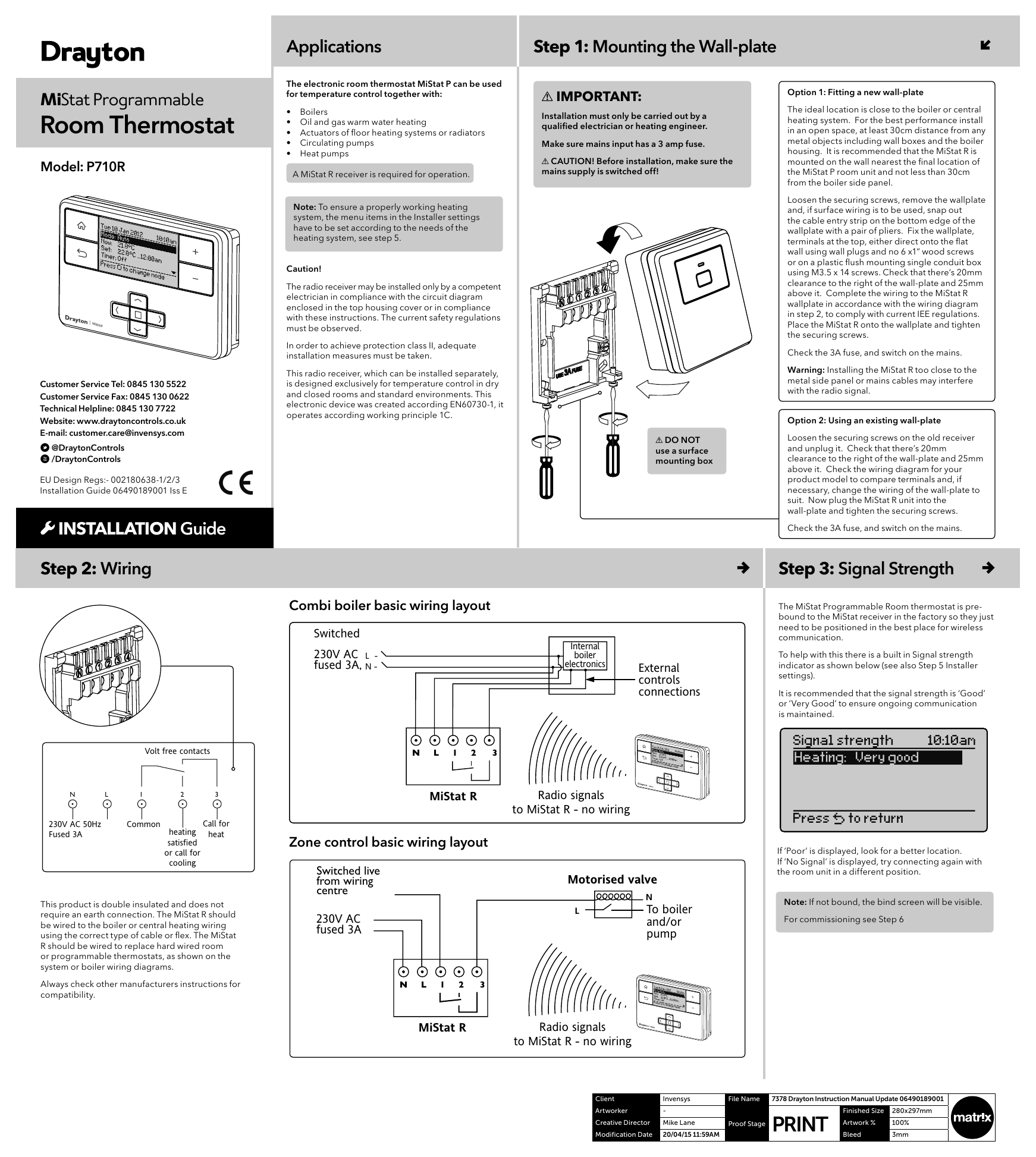
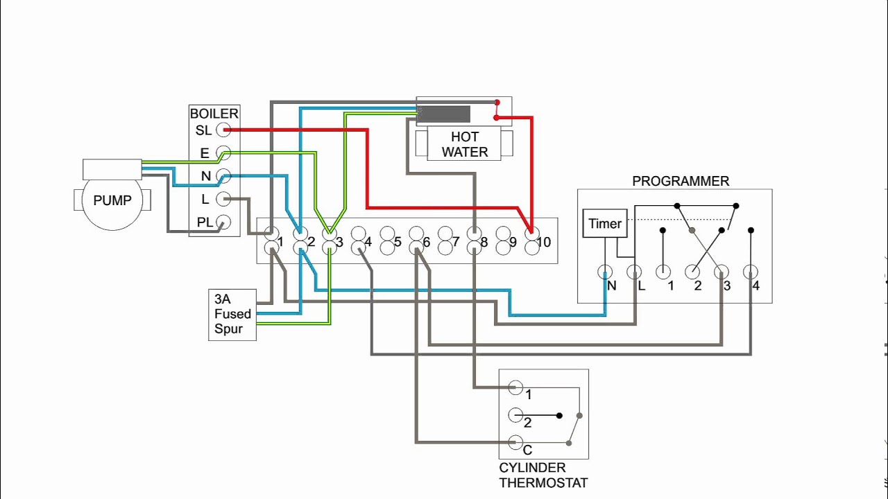
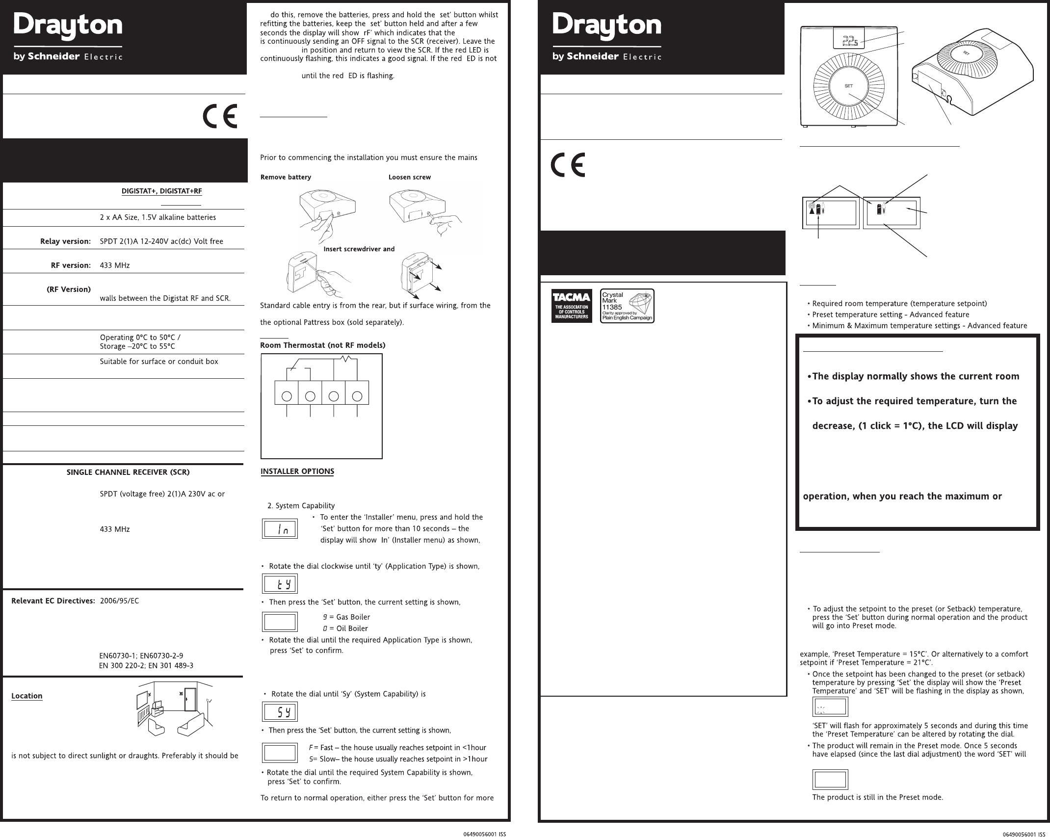
Drayton wiring diagram. Get free help tips support from top experts on drayton hts3 wiring diagram related issues. Gravity hot water pumped central heating system schematic. Drayton is one of the uks leading heating control brands and part of schneider electric a global technology group focussed on helping customers make the. Find solutions to your drayton hts3 wiring diagram question. Drayton rts1 manual online. Programmable room thermostat wireless.
Drayton lp241 wiring diagram they all come with wiring diagrams but finding which wire end up had a response from the manufacturer and the drayton lp is a direct. Load of 21a v ac. Rf701 thermostat pdf manual download. Dec 28 2016 1 please can anyone supply me with a wiring diagram to fit a drayton lifestyle lp711 timeswitch to a vailant ecotec 832 exclusive. Probably the highest number of requests draytons technical team receives every week is for help with wiring diagrams using the lwc1 or lwc3 wiring centre. Drayton lwc1 wiring centre wiring guide wiring centres designed to simplify wiring installations and circuit checking lose some of their value if they are not in themselves easy to understand and use.
Drayton lp822 wiring diagram instructions for programming drayton central heating controls that may be downloaded free. Status not open for further replies. It acl and drayton room thermostats subject to a maximum. View and download drayton rf701 installation instructions online. Drayton 3 port valve wiring diagram wiring diagram is a simplified enjoyable pictorial representation of an electrical circuit. The drayton lwc1 wiring centre has been introduced to meet this requirement.
Page 2 the hts3 should be installed approximately one from the wiring centre or junction box run the base of the hts3 should be held in good the two setting marks outside the third of the way up the hot water cylinder and at sufficient 3 core electrical connecting cable to. Each installation is different depending on the configuration and the controls used so to try and help as much as possible the tech team has created 24 diagrams covering the most popular layouts. The lwc1 is suited to all popular central heating and hot. It shows the components of the circuit as simplified shapes and the aptitude and signal contacts in the midst of the devices.
Gallery of Drayton Wiring Diagram