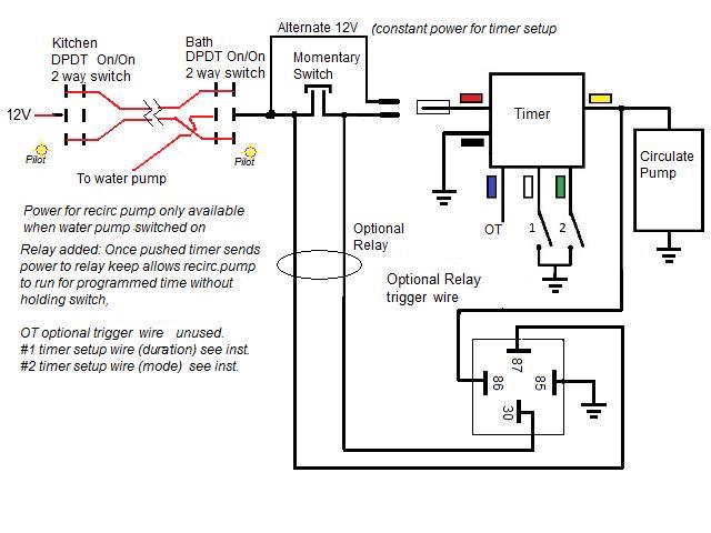
When you need to control a dc motor such as a dc linear actuator you usually need to be able to swap the polarity on the wires going to the motor. If you have a 4 wire winch controller you connect the two out wires to 2 and 1 and or get the right diagram and ill.
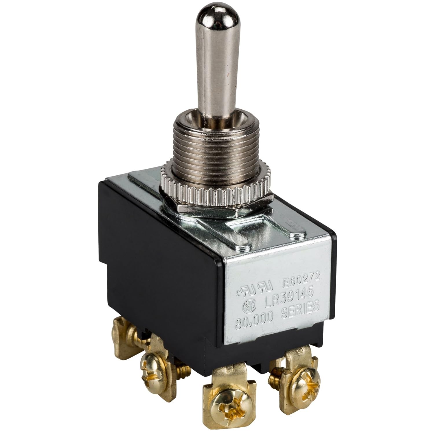
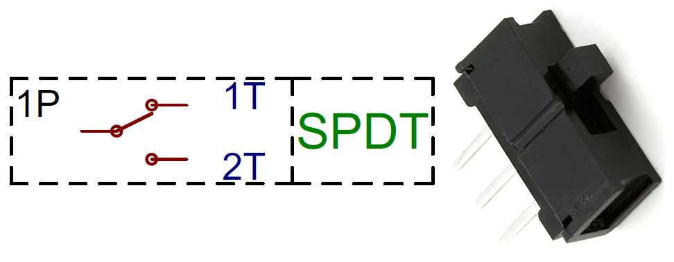
How To Wire A 6 Pin Toggle Switch Quora
Dpdt momentary switch wiring diagram. Toms trains and things 66749 views. It shows the elements of the circuit as streamlined forms and the power as well as signal links in between the gadgets. We will now go over the wiring diagram of a dpdt toggle switch. Wiring a dpdt switch 2 methods explained duration. Push button switches are the classic momentary. Wire a dpdt rocker switch for reversing polarity.
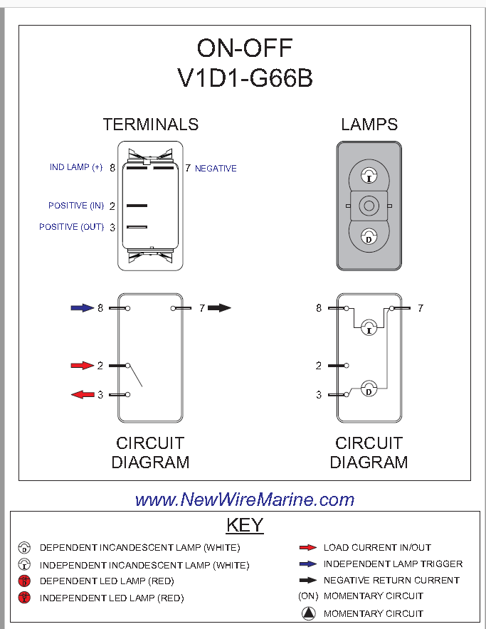
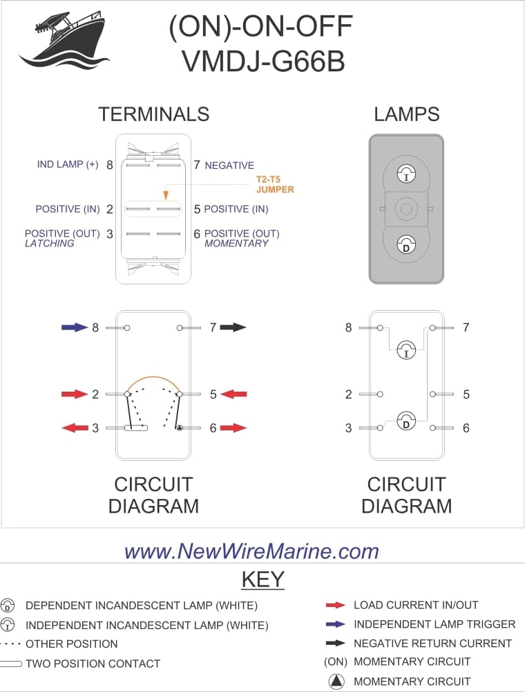
Dpdt double pole double throw. A wiring diagram is a streamlined conventional photographic depiction of an electrical circuit. Wiring a 3 position onoffon dpdt switch duration. Examples of momentary switches push button. Most often momentary switches are best used for intermittent user input cases. Sep 8 this dpdt illuminated rocker switch has two dependent lamps one top and one at the bottom.
The wiring diagram to the right shows how the. Collection of 6 pin dpdt switch wiring diagram. It is off at the bottom on in the center and momentary on at the top. Momentary switches are switches which only remain in their on state as long as theyre being actuated pressed held magnetized etc. This rocker is perfect for an engine offrunstart switch. These terminals receive the power necessary to drive the loads on terminals 1 and 5 and 2 and 6.
The wiring diagram below will demonstrate how to to wire and power this 12v 20amp on on off 3 way carling contura rocker switch. When the dpdt switch is switched one way flipped upward in the diagram the lamp and buzzer are both on while the. Double pole double throw switch dpdt circuit. Below is an example of a circuit which utilizes a double pole double throw switch. A dpdt toggle switch has 6 terminals. Some clarity on the wiring of a contura v momentary on off on dpdt switch.
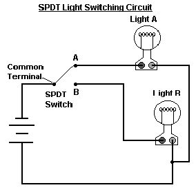
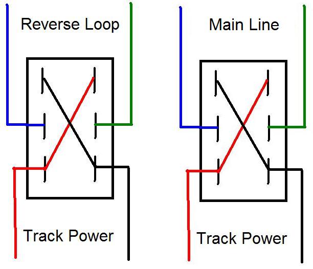
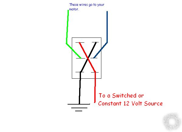
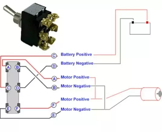
Below is the schematic diagram of the wiring for connecting a dpdt toggle switch. Terminals 3 and 4 represent the toggle switch. A pair of on on switches which operate together shown by the dotted line in the circuit symbol. A double pole double throw switch is used for this purpose but you have to wire it up correctly. Stuff like reset or keypad buttons. A dpdt switch can be wired up as a reversing switch for a motor as shown in the diagram below.
You can see above how a double pole double throw switch can allow a circuit to be in 1 of 2 modes. The vmdj is a unique dpdt momentary rocker switch.
Gallery of Dpdt Momentary Switch Wiring Diagram