One wire at a time carefully solder them one after the next to the controller. Wiring diagram product size operation constant voltage part no.
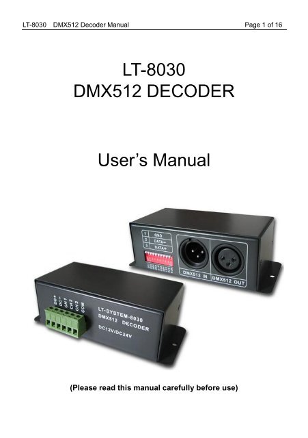
File 1369398026 By Ultraleds Issuu
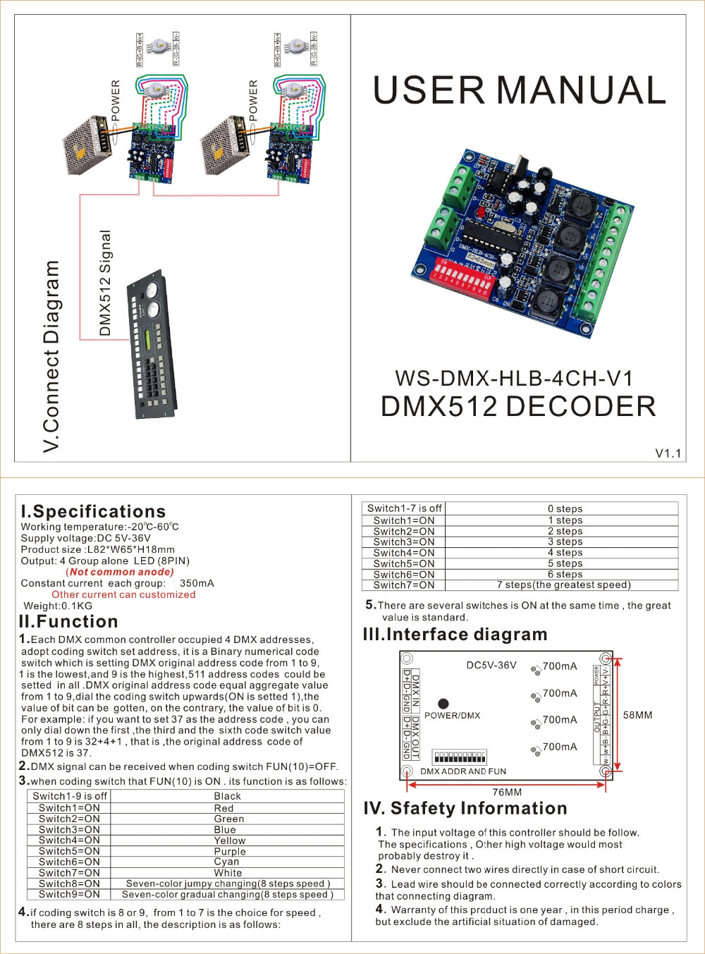
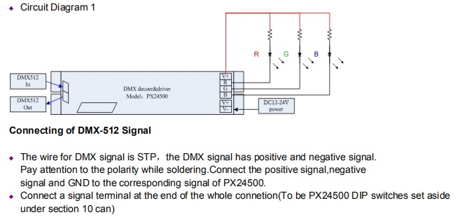
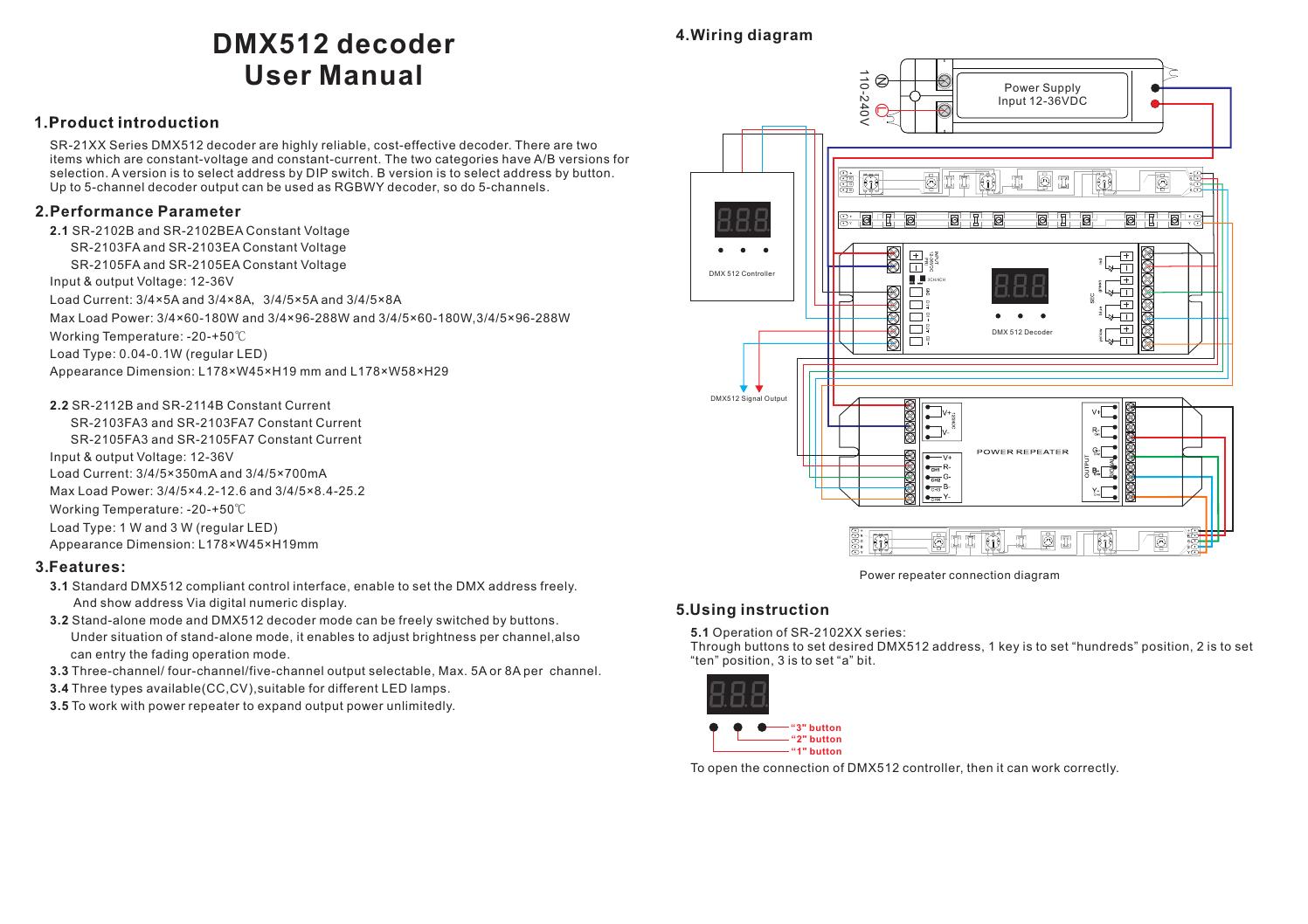
Dmx512 decoder wiring diagram. Ultra pro 5ch rdm dmx512 decoder dmx512 rdm decoder rdm function can realize intercommunication between dmx master and decoder. Using instruction compatible with dmx1rgbw constant voltage 980 650 1055 530 power supply 12 36vdc n l 110v 230vac dmxrec din d d d d gnd 0 5 0 9 0 9 dmx512 decoder v v w b g r power input dmx master rgbw or cdw led strip choose channel. Dmx512 rdm decoder to owr pply g. A quick guide to what you really need to know about dmx512. To open the connection of dmx512 controller then it can work correctly. No tees are permitted.
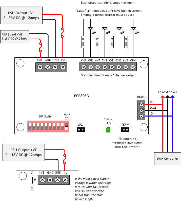
Dmx512 decoder constant oltagev dmx512 decoder d connectconstant voltage c1 2v 2 4v dmx connectsignal model nodcv 03 model nodcv 03 dm x si gn al wiring diagram 2 dmx512 controller modelnodmx500 24g wireless dmxdmr signal converter model nodsc 24 24gwirelessdmxdmr signal converter model nodsc 24 optional dc1 2 4 dmxdc12v 24v. Below is a circuit diagram that illustrates how to wire the dmx512 pixelcontrol decoder to pixelcontrol lights a power supply and the dmx controller. This compact decoder works with dmx512 console 256 level brightness control. Star wiring is only allowed in conjunction with an opto splitter. Strip all 18 of insulation of each wire both ends. In this diagram the easy stand alone dmx controller is used to control the pixelcontrol led lights but you can use any console that outputs standard dmx.
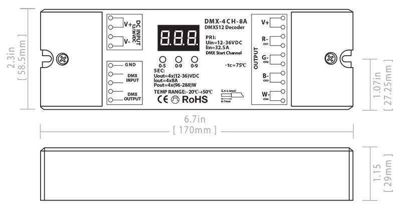
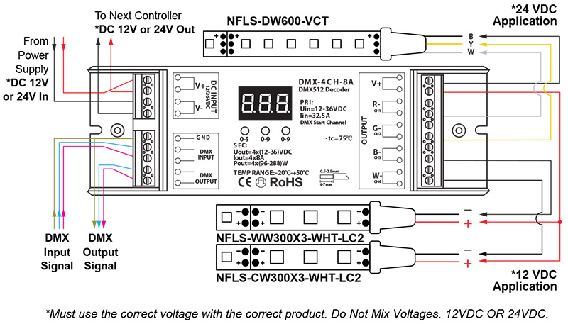
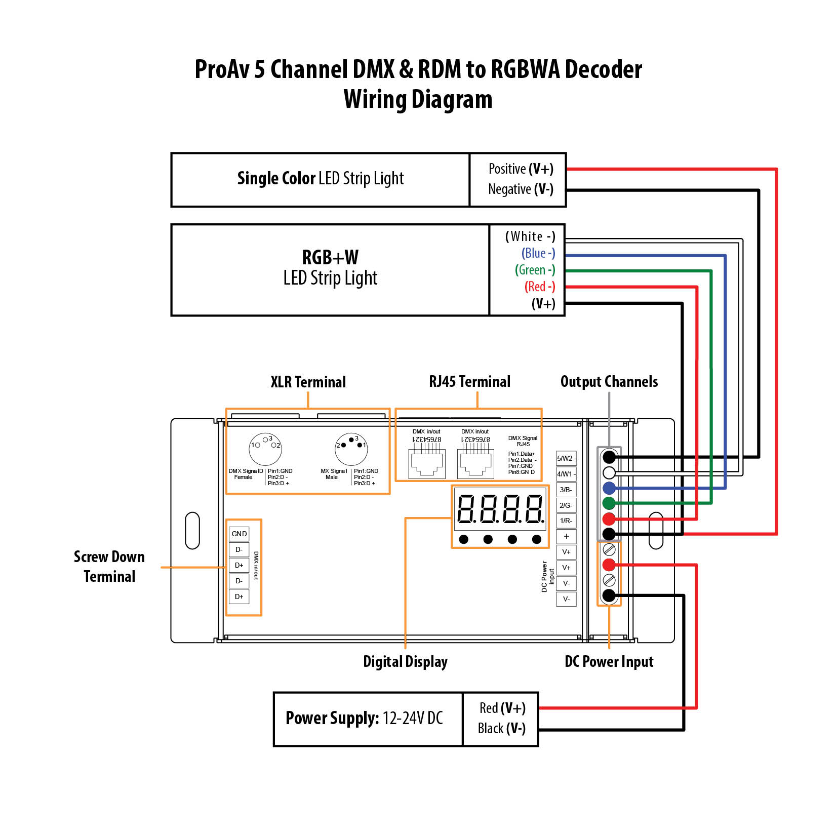
Input voltage output current output power remarks 16400 mm 7300 mm 3800 mm. Wire xlr dmx inout rj45 dmx inout output for led screw dmx inout dc power input digital display l ire trac gb l ight red green blue t dmx512 rdm decoder rdm function can provide the interface between dmx master and decoder. Lt 840 decoder is designed via advanced micro electronic control technology to convert universal dmx 5121990 signal into pwm signal. Lay it out flat and place the led display on the un soldered end note where the wires should be soldered. Using a razor blade start by splitting the cable about 05 1 long both ends. For example you can set dmx decoders address by dmx master console.
Below is a circuit diagram that illustrates how to wire the dmx512 pixelpro decoder to pixelpro lights a power supply and a dmx controller. Cable shield may be grounded at one end only preferably at the control console. Lt 840 dmx512 decoder manual thank you for choosing lt 840 dmx512 decoder. Maximum cable length is 1800 ft when used for dmx only. Wire to cirit rr o. Keep signal lines away from power lines to avoid inductive coupling and signal corruption.
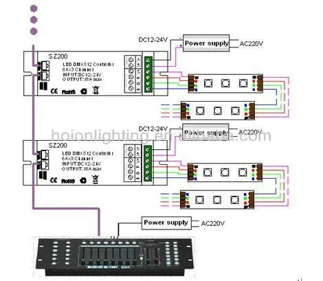
Dmx decoders address 001 is controlled by zone 1 dmx decoders address 005 is controlled by zone 2 dmx decoders address 009 is controlled by zone 3 dmx decoders address 013 is controlled by zone 4 dmx decoders address 017 is controlled by zone 5 dmx decoders address 021 is controlled by zone 6. 0 100 brightness or different effect. In this diagram an easy stand alone dmx controller is shown but you can use any console that outputs standard dmx. All wiring must be in a continuous run and daisy chained.
Gallery of Dmx512 Decoder Wiring Diagram