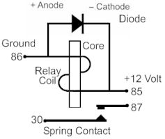
It is in the reverse biased position when the relay is turned on. Relay coil r1 is energized to ground at headlamp ground wire.

Relay Switch Circuit And Relay Switching Circuit
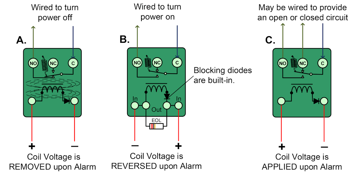
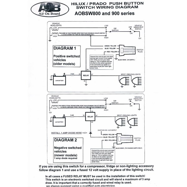
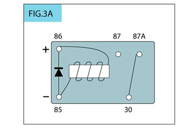
Diode relay wiring diagram. Hayden 3653 optional diode pn. Suggested electric fan wiring diagrams converting a 12 volt switch into a ground switch these diagrams show the use of relays onoff sensors onoff switches and onoff fan controllers. The headlamp filaments to ground the doors open as follows. Learn how to wire a 4 or 5 pin relay with our wiring diagrams and understand how relays work. Protects relay from. Relays with de spiking diodes a de spiking clamping diode is connected in parallel with the relay coil.
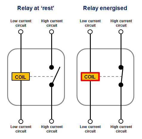
Dozens of the most popular 12v relay wiring diagrams created for our site and members all in one place. Therefore no current will flow through the diode. Using a relay with a diode across the coil can prevent this damage by absorbing the high voltage spikes and dissipating them within the coildiode circuit this is known as a blocking or quenching diode. Relay coils r2 and r3 are not energized because the. Relay coil terminals have no polarity unless the relay coil is protected by a diode inside the relay in which case the coil terminal wired to the diodes anode must be connected to. When the relay control circuit is opened turned off current stops flowing through the coil causing the magnetic field to.
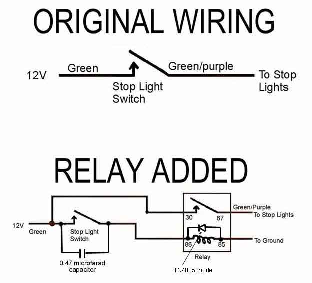
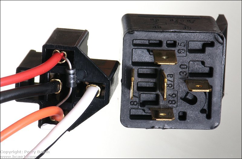
If you need a relay diagram that is not included in the 76 relay wiring diagrams shown below please search our forums or post a request for a new relay diagram in our relay forum. The following diagrams show some common relay wiring schemes that use 4 pin iso mini relays. In5408 make sure the diode band is facing toward the fan or relay and away from ground. Adding driving lights that come on with. A one way diode in the ignition switch side of the harness f. The control circuit is energized when the headlamps are turned on through the light blue wire.
The circuit protection specialists.
Gallery of Diode Relay Wiring Diagram