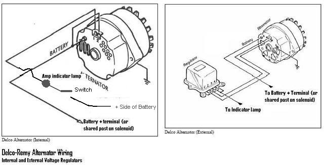
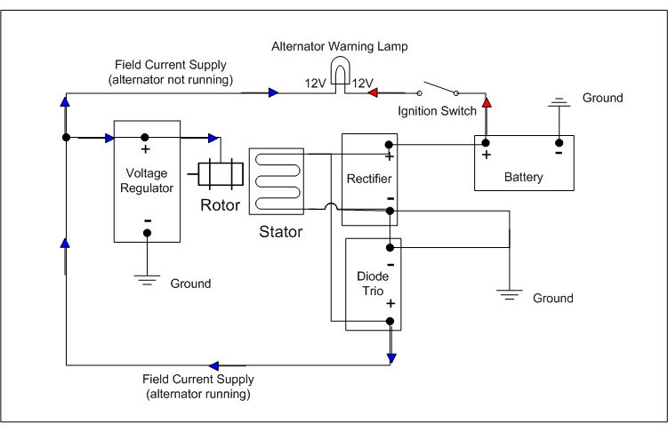
How to wire an external voltage regulator on a gm vehicle. The following schematic shows the wiring circuit of delco remy 1118200 type.
12v Generator Wiring Delco Remy Voltage Regulator Wiring
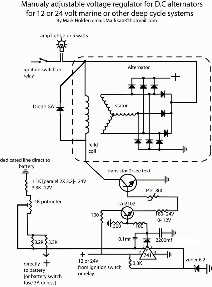
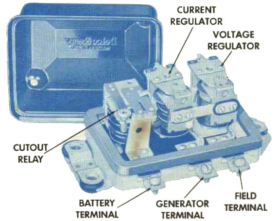
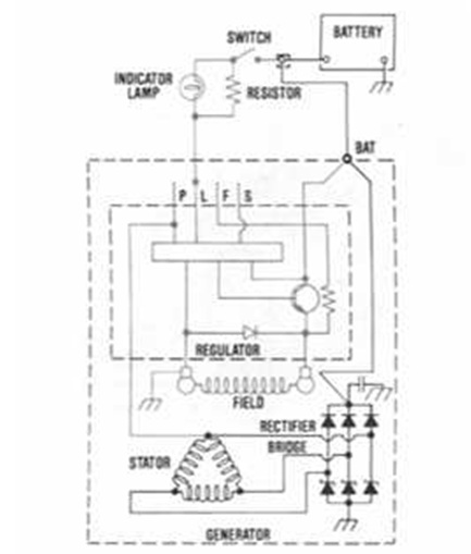
Delco remy voltage regulator wiring diagram. The series windings in the cutout relay and current regulator are shown in red. Wiring diagram for garden tractors with a delco remy starter generator here is an example wiring diagram for a garden tractor that is equipped with a delco remy starter generator. The below diagram also shows our 5 prong 3 position ignition switch and our 4 prong mechanical voltage regulator. The series winding in the voltage regulator is shown in blue. The ac delco 3 wire alternator was used in most general motors products and many types of heavy equipment for a long time which makes it readily available. See delco remy service bulletin ir 180 and ir 185 for specifications.
Wiring diagram figure 3 will show that regulation begins at the point where the shunt windings are connected to the series circuit. Any small resistance added to the circuit. Between those years you may have the cs 130 or the cs 130d alternator. Three unit regulator shown the shunt windings in the cutout relay and voltage regulator are shown in dashed blue. The early gm alternator is the 10dn series alternator and was used on gm vehicles from about 1963 1970. The wiring hookup is the same for the cs 130 and cs 130d alternators.
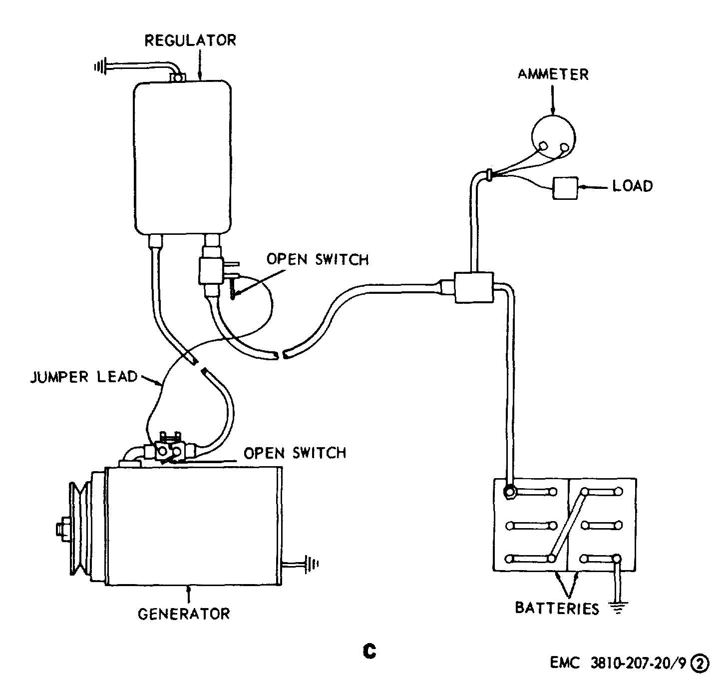
Retrofitting old stlye delco remy regulator to new style delco remy 50vr regulator. 1995 1998 was a transitional period for the cs 130. Wiring diagram for ac delco alternator inspirationa fresh 3 wire. The gm delco remy cs130 alternator was used on gm vehicles from about 1986 1996. Wiring instructions for the early gm delco remy external regulated alternator. Check voltage regulator setting by fixed resistance method.
Delco remy voltage regulator wiring diagram.
Gallery of Delco Remy Voltage Regulator Wiring Diagram