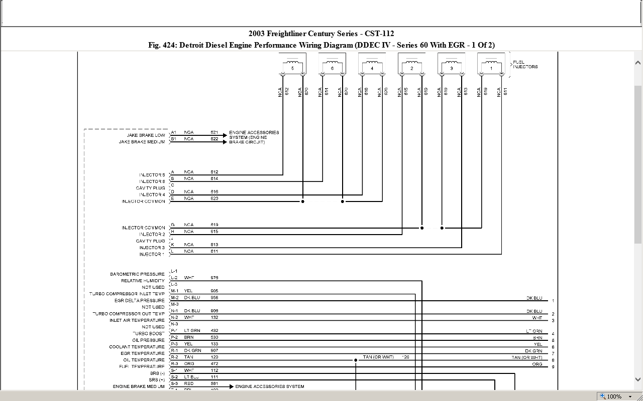
There are two links on the vehicle interface harness vih. 4 for a full view of the ddec iii wiring diagram the engine side.

Ddec V Vezetekdiagram A Detroit Dizel Sorozatban 60 Ecm Roc
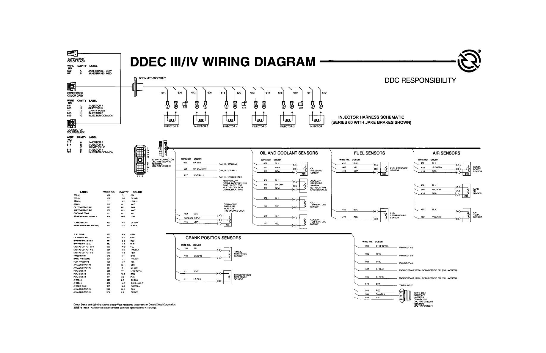
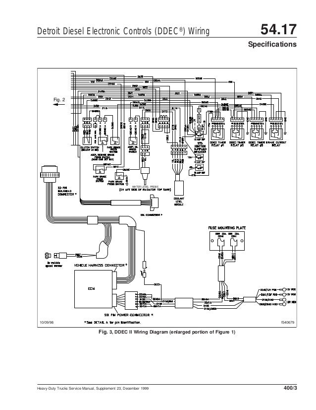
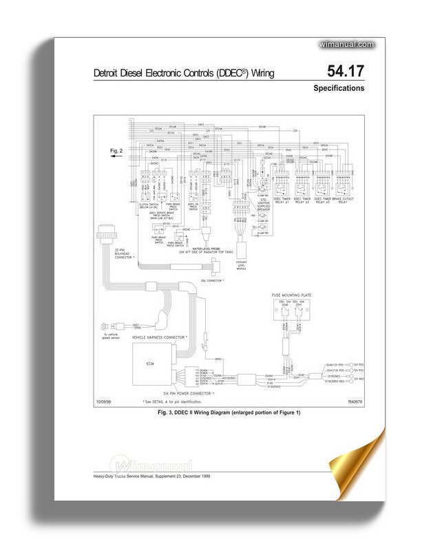
Ddec 3 wiring diagram. 7 for a full view of the ddec iii wiring. Detroit series 60 ecm wiring diagram new detroit diesel series 60. The detroit diesel series 60 ddec iii iv v vi wiring diagrams are also known as electrical schematics or circuit diagrams. Ddec ii wiring diagram detroit sel wiring diagrams wiring diagrams dimensions ddec ii wiring diagram wiring diagram is a simplified welcome pictorial representation of an electrical circuit. 1996 freightliner wiring diagram freightliner auto wiring diagrams. However you want to look at it.
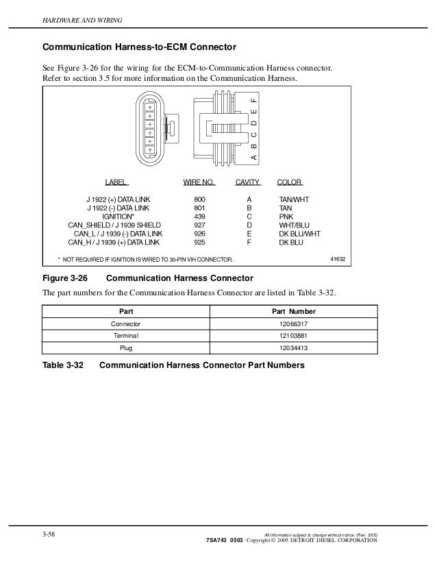
Pinouts diagrams and more for the ddec 3 and 4. Pin wire color signal type function connector e 1 blk pwm. Oct 27 detroit diesel ddec iii and iv ecm vehicle and engine connectors. The wiring diagrams cover both the series 60 engine harness and series 60 vehicle interface harness. Detroit diesel series 60 ecm wiring diagram gallery detroit diesel ddec vi series 60 mcm egr engine harness schematic to. Pinouts diagrams and more for the ddec 3 and 4 engine control modules ecms are used with detroit diesel series 50 60 and 6v92 engines.
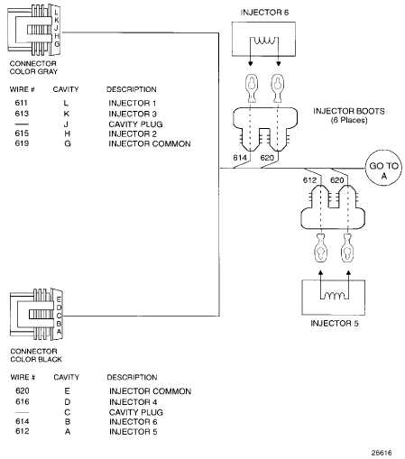
The engines differ because detroit diesel works with the builder of the vehicle to. 24 mvb1c injector cyl 3 pin 1 25 mvb1 injector common cyl 3 pin 2 26 mvb1a injector cyl 1 pin 1 27 mvb1 injector common cyl 1 pin 2 28 startb nc 29 a16 doc outlet temp sensor 30 a01 dpf outlet pressure sensor table 3 5 mcm connector mbe 900 1 of 4 c sample 3 8 all information subject to change without notice. Detroit series 60 ecm wiring diagram. Updated on april 20 busdieseldude. List of files in the detroit series 60 wiring diagram. Ddec i ddec ii and ddec iii iv schematics.
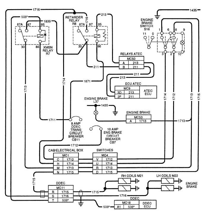
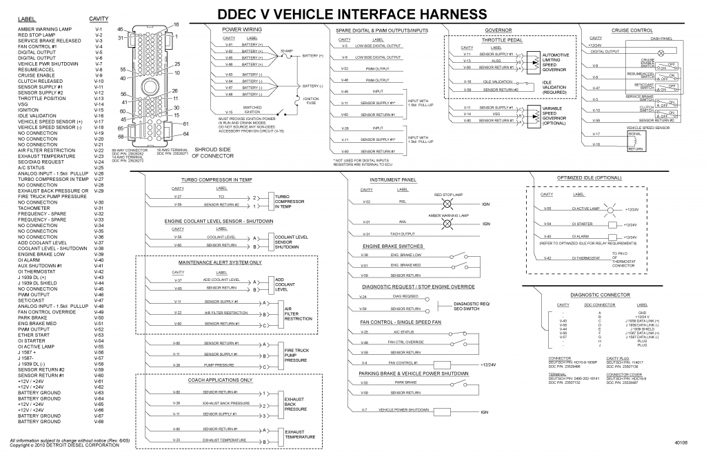
The 1st is a wiring diagram dash to sensors or sensors to dash lights. Hardware and wiring ddec v supports three independent data links. One link is based on sae j1708 and the second is sae j1939. Ddec i ddec ii and ddec iii iv schematics ddec i controls the timing and amount of fuel injected into each cylinder. The system also monitors several engine functions using various sensors that send electrical signals to the main electronic control module ecm. The eh 68 pin tyco connector pinout for the series 60 is listed in table 3 5 and table 3 6.
6 for partial detailed views of the full view of the ddec iii wiring diagram the engine side. Ddec iv application and installation manual 341 vih design the following criteria are to be used when designing the vih. 3 for partial detailed views of the full view of the ddec ii wiring diagram. It shows the components of the circuit as simplified shapes and the facility and signal associates in the midst of the devices. Vih design the vih 30 pin connector is designed to accept 18 gage 075 080 mm2 standard wall thickness cable only. Unless you can point out the actual location of the vpods to ecm.
Gallery of Ddec 3 Wiring Diagram