12p15mmsq analog inpu electrical househome wiring electricalhome wiringelectrical house. Control panel wiring diagram control panel wiring diagram.

File Dcs Deltav Png Wikimedia Commons
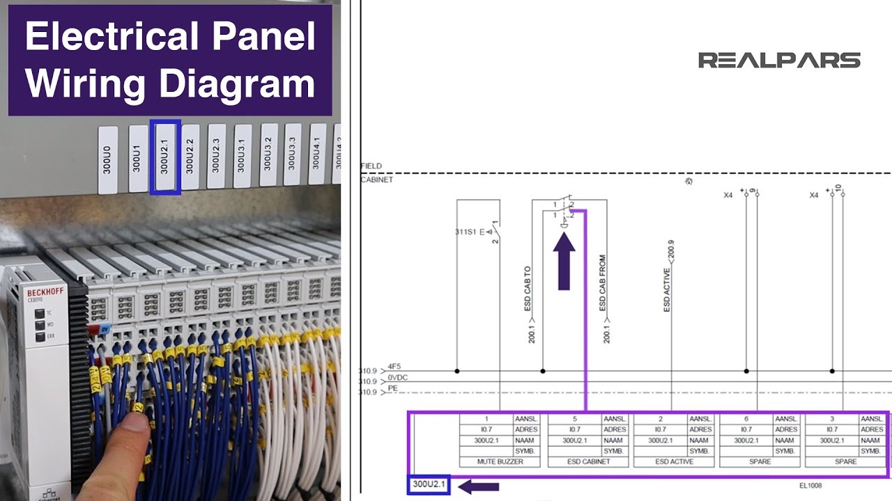
Dcs panel wiring diagram. Dsc powerseries neo alarm com module programming wiring things you need to know duration. A field junction box is used to concentrate the signals into multi conductor homerun cables or main cables. Note that these diagrams are without a barrier or isolator fuses and surge protector for keeping it very simple and understandable. In this article we are sharing the basic concepts of plc and dcs control systems wiring diagrams for digital input di digital output do analog input ai and analog output ao signals. This is the master wiring diagram for a power 864 main panel. See the alarm wiring guide for more information.
This guide assumes that all of the components will work together. The power 864 supports 64 different zones but only 8 zones are available with the main board. Limited warranty if telephone lines are used to transmit alarms they may be out of service or busy for certain periods of any products returned to dsc which have the installers lockout option enabled and time. Alarm system store 11337 views. Distributed control system dcs and programmable logic controller for emegency shutdown system esd. Existing dcsplc hook up diagram 116 116 14 annexure iii tentative bill of material for dcs.
The homerun cables then terminate in a remote or marshalling cabinet where the signals are marshalled reorganized as necessary to efficiently terminate at the io interface of the dcs or plc system. The new dcs and plc panels and consoles need to be installed in the existing. Learn to wire a dsc alarm panel in five minutes. Dcsplc panel wiring diagram. Actual wiring diagrams and pictures are provided for real dsc products. Electrical house wiring 3 gang switch.
Gallery of Dcs Panel Wiring Diagram