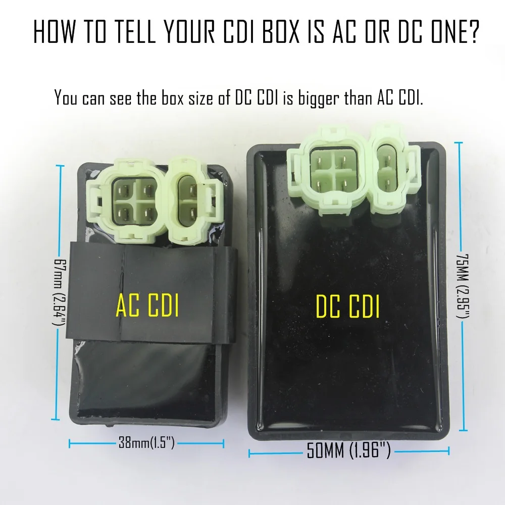
A dc cdi can operate without a battery connected the 470 uf capacitor on the dc dc converter input will get a pulse of. The input to the cdi unit is derived from two sources of the alternator.
Ada73e Chinese Scooter Dc Cdi Wiring Diagram Wiring Resources
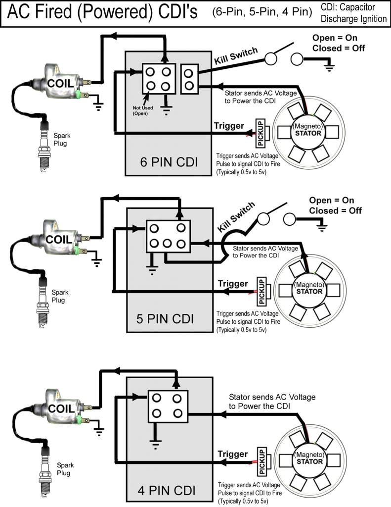
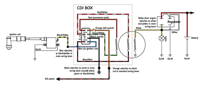
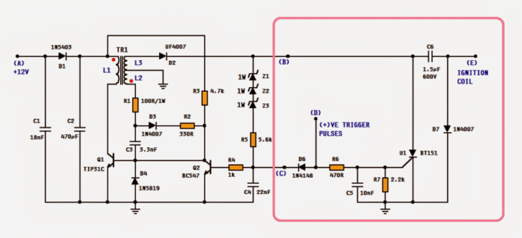
Dc cdi wiring diagram. Killswitch and ac are separate. Referring to the above capacitor discharge ignition circuit diagram we see a simple configuration consisting of a few diodes resistors a scr and a single high voltage capacitor. Provided below is an online pdf document for lamberts bikes 4 pin dc cdi wiring diagram. Weve even included standard wire colours where appropriate. Researched and submitted by. This makes the procedure for building circuit simpler.
On the other hand the diagram is a simplified variant of the structure. Like all good motorcycle engineers lamberts bikes have produced part specific electrical wiring schematics. Each part should be placed and connected with different parts in specific way. Gy6 dc fired cdi wiring diagram here is the chinese engine code chart with the example of the jog 2stroke gy6 engines are on the fron bottom left had side near the centerstand pivot. Mar 27 2013 163214 gmt 5 by rune75. Each diagram includes the part and associated parts all in one wiring diagram.
Provided below is an online pdf document for lamberts bikes 6 pin dc cdi wiring diagram. A dc cdi is the one in which the high voltage 200 400vdc is converted from 12v supply voltage. Like all good motorcycle engineers lamberts bikes have produced part specific electrical wiring schematics. 6 pin cdi box wiring diagram 6 pin cdi box wiring diagram 6 pin dc cdi box wiring diagram every electric structure is made up of various unique components. Abu hafss studying the circuit we see that it has two parts ie. Weve even included standard wire colours where appropriate.
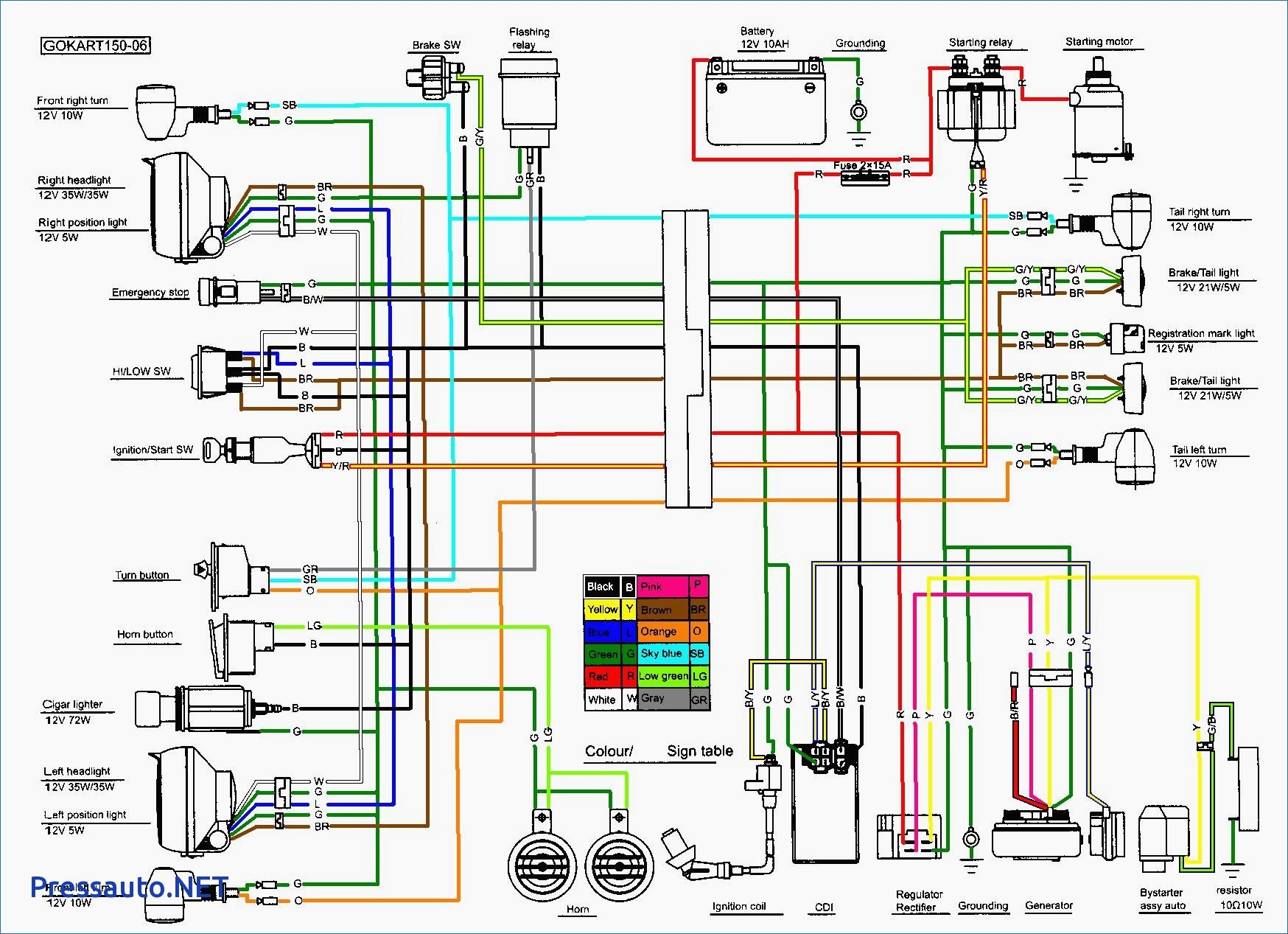
Note that the red wire from the stator to the cdi will not be on a dc fired system. Dc cdi wiring diagram wiring diagram gy6 cdi wiring diagram the diagram offers visual representation of an electric arrangement. If not the structure will not work as it ought to be. Each diagram includes the part and associated parts all in one wiring diagram. All 6 wires come from different places. Cdi circuit using an scr a few resistors and diodes.
On the last pages you will find a wiring diagram where you can see how the cdi is wired. 13 thoughts on pinout diagram of the dc cdi david wassell i have a yg6 150cc go cart with no spark i replaced coilstatorcdi starter relaynew battery have power up to key ignition but when you turn key to start nothing happens have lights starters good my cdi box has 6 pins but my connector has 5 wires which hole should the 2. The cdi unit enclosed in the pink box and the remaining circuit on the left is high voltage converter.
Gallery of Dc Cdi Wiring Diagram