Crossover cable color code tia 568b following table illustrates tia 568b color coding scheme which is applied on left end of cable in crossover cable wiring diagram. Remember the rj45 wiring order.

Rj45 Wiring Diagram Crossover Generatorisasi 2006 Rmnddesign Nl
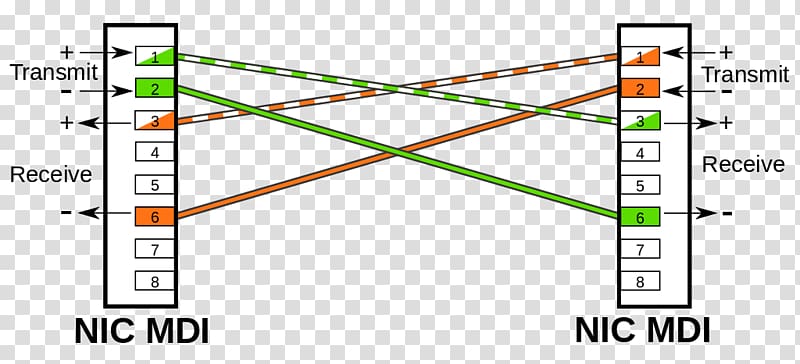
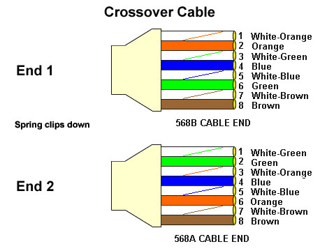
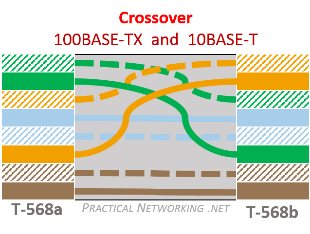
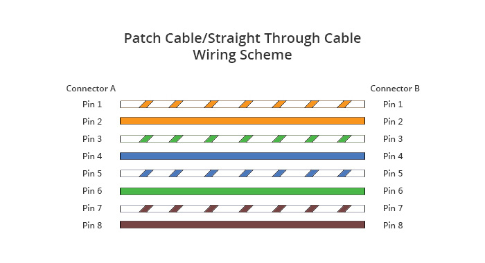
Crossover cable wiring diagram. Two computers via their network interface controllers or two switches to each otherby contrast patch cables or straight through cables are used to connect devices of different types such as a computer to a. This effectively crosses over the connections between transmit and receive pins. In normal setups youll use a straight through cable where the wires are the same on each side. The crossover cable diagram shows the transfer and receive wires are crossed this allows the computers to talk directly to each others. Crossover cable wiring diagram we can see in above diagram that left side is following 568b color coding and right end is following 568a color coding. It is most often used to connect two devices of the same type eg.
Crossover wiring diagram. Another way of remembering the color coding is to simply switch the green set of wires in place with the orange set of wires. Click to find view print and more. This diagram shows the sequence of colored wires used for eai cross over cable tia 568a standard. Eiatia 568b also known as standard ethernet is the type of cat 5 connection used to connect ip security cameras and network video recorders nvrs in ip surveillance systems. The patch cable connects two different devices to each other like a pc and a switch.
Rj 45 crossover ethernet cable a good way of remembering how to wire a crossover ethernet cable is to wire one end using the t 568a standard and the other end using the t 568b standard. The complete ethernet pinout cable wiring reference with wiring step by step guide. The following scenarios will explain the different applications. If you are creating a crossover cable please click here for the crossover cable diagram. An ethernet crossover cable is a crossover cable for ethernet used to connect computing devices together directly. The following ethernet crossover cable diagram represents the wiring for a cat5 and cat5e crossover cable.
Crossover cable wiring pinout and diagram crossover cable wiring pinout and diagram a crossover cablealso known as xover cable follows the t568a schemeat one end and t568b schemeat the other. Rj45 pinout diagram shows wiring for standard t568b t568a and crossover cable. Click to check the right one for you or print as reference. T1e1j1 rj48 cable diagram the following illustration provides the wiring connections for straight or crossover cables. Cat 5 crossover cable is used to create 2 node untwisted pair network which can connect two computers. In brief a crossover cable connects two devices of the same type to communicate together like a pc to a pc or a switch to a switch.
The transmit pins on each connector are connected to the receive pins which is at the other end of the cable. You can easily make connection with the crossover cable in your home.
Gallery of Crossover Cable Wiring Diagram