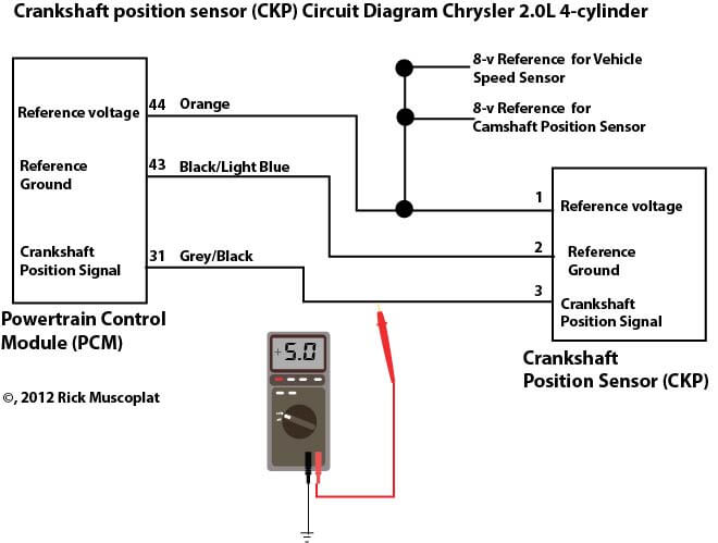
The illlustrations and info in this page apply only to 1996 1997 1998 dodge ram pickups vans and dakota with a 39l 52l or 59l gasoline engine that use the 3 connector pcm. Then using the meter red lead back probe the black ground wire at the harness connector or ckp sensor.

I Have A 2001 Chevy S10 With A 4 3 L Vortec I Had Some
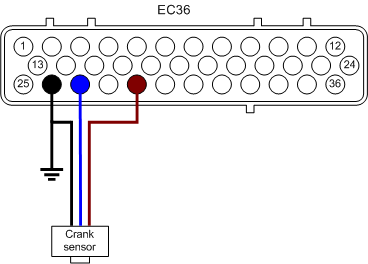
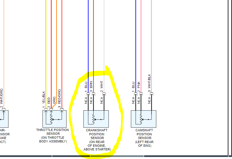
Crank sensor wiring diagram. This video is dedicated to cam and crk sensor testing and operational parameter but from an electrical and wiring diagram interpretation point of view. Now touch your dmm red lead to the green signal wire on the harness connector or ckp sensor. Sign up today to access the guides. Your dmm should register about 200mv to 300mv. You should be able to tell from a wiring diagram a good one which wire goes to which terminal. Blu wire carries crank signal to pcm.
A wiring diagram makes it easier to check for shorts to ground or power and of course check for continuity between the crank sensor and the pcm. All three wires connect directly to your dodge dakota or durangos fuel injection computer. 3 wires on mine. The crank sensor is a 3 wire hall effect sensor. If neither wire has current theres a failure in the sensor circuit. Brnyel wire feeds chassis ground.
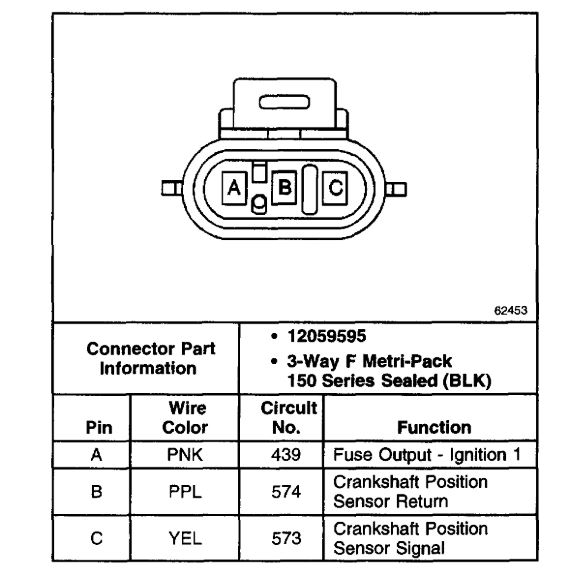
This means that one wire feeds it with power one wire feeds it ground and the other takes the ckp signal to the computer. Touch one of your meter probes to either one of the sensor wires and the other to the other wire. Pink is 12v yellow is signal and purple is supposedly groundsignal return. Crank sensor wiring diagram 2001 2005 17l honda civic. Ask an assistant to crank the engine for a few seconds. Yelblk wire feeds 12 volts from pgm relay.
Crank sensor wiring issues. The cam and crk sensors are types of speed. Dec 24 2011 327am. Pink purple and yellow. Crank the engine for a few seconds. Learn how to access vehicle repair guides and diagrams through autozone rewards.
Have your helper crank or start the engine. The connector on the sensor itself has male spade terminals. Pin a is 12v pin b is ground and pin c is signal. Check your meter display and compare your reading to your manual specifications. Crankshaft position sensor wiring diagram. Crankshaft position sensor wire color id and description.
In most cases youll see a fluctuating signal.
Gallery of Crank Sensor Wiring Diagram