For airplanes that are to have a ka210 170 2vr600a replacement kit installed. Aircraft alternator owners manual list of illustrations page figure 21 alternator simplified electrical diagram 2 1 figure 22 stator wiring diagram typical 2 2 figure 23 typical alternator cutaway basic components 2 3 figure 24a es 10024 front view 2 5 figure 24b es 10024 rear view 2 5 figure 25a alv 9610 front.

Bd 3231 172 Wiring Diagram Manual 172rwd08 Schematic
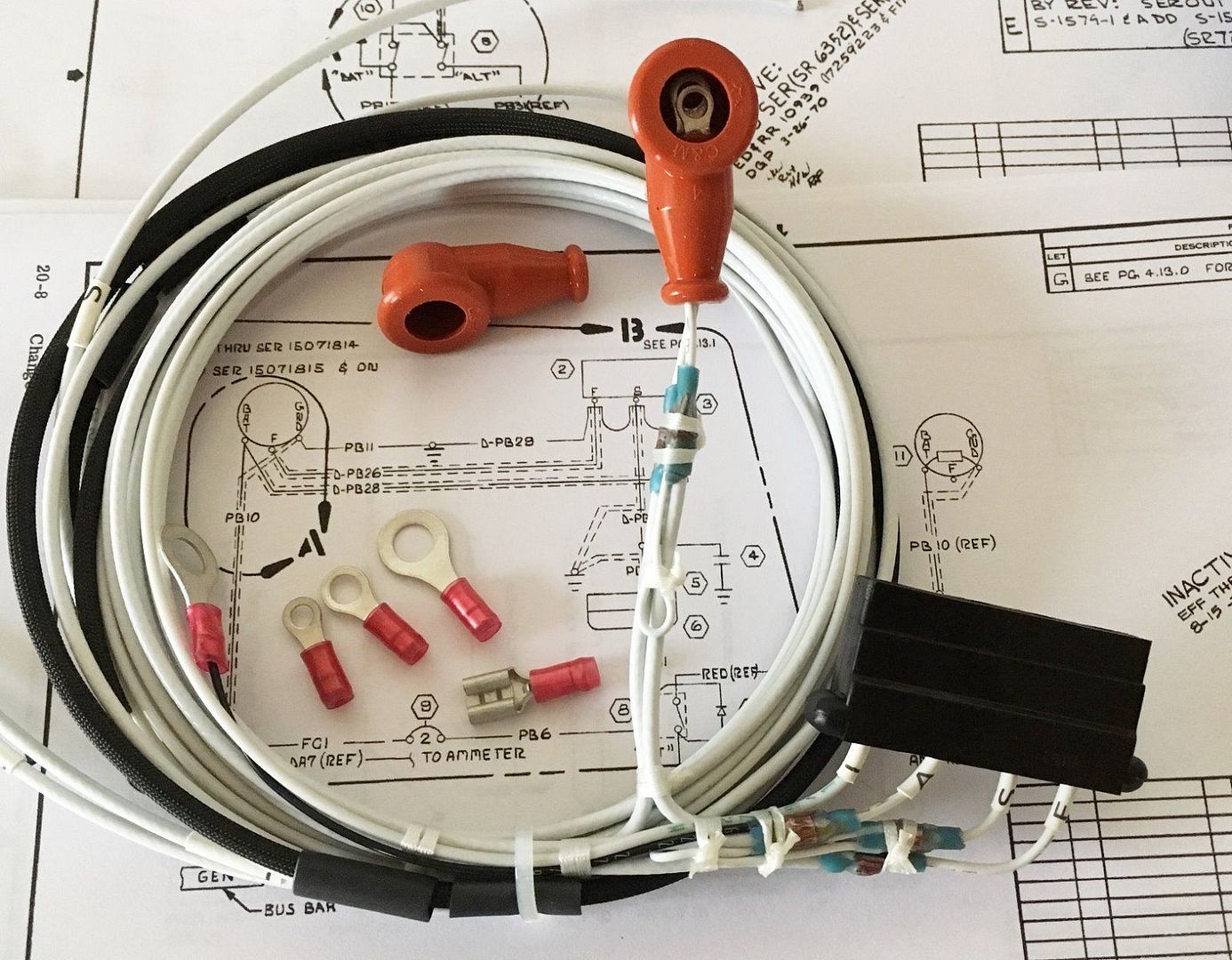
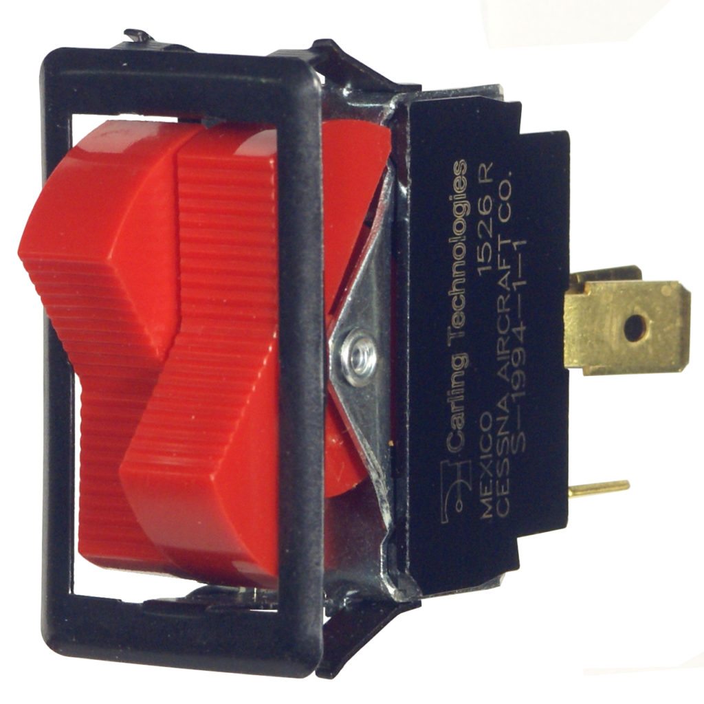
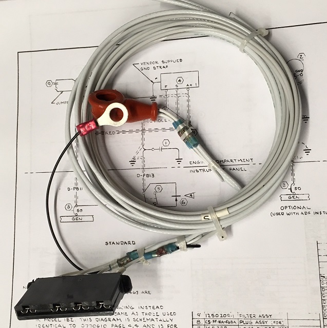
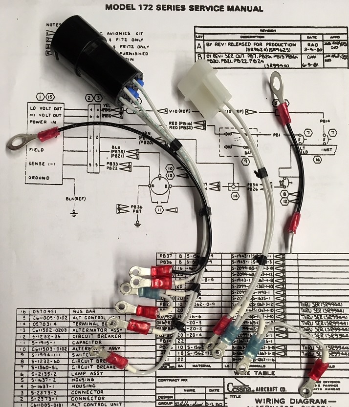
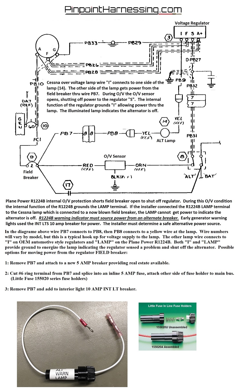
Cessna 172 alternator wiring diagram. The left side of the master switch provides 5 amp power to energize the alternator. The red wire is the current supply from the bus that powers the voltage regulator. Aircraft wiring usually consists of tin coated copper stranded wire covered by insulation. There is one thing that kind of caught me off guard though. Refer to the applicable service manual and wiring diagrams as necessary 2 install a vr660 voltage regulator. That should at least resemble a typical cessna 172 its.
The alternator or battery bus connects directly to things that use electricity like the flaps motor. The orange wire and the black wire are used to sense alternator voltage directly from the b terminal and ground connection at the alternator. 1 make sure there is continuity in the wire from alternator bat terminal to a pin on the voltage regulator wire harness. The orange wire connects to b. The switch is split to separate the two systems. The yellow wire is the field wire that connects to the alternators f1 terminal.
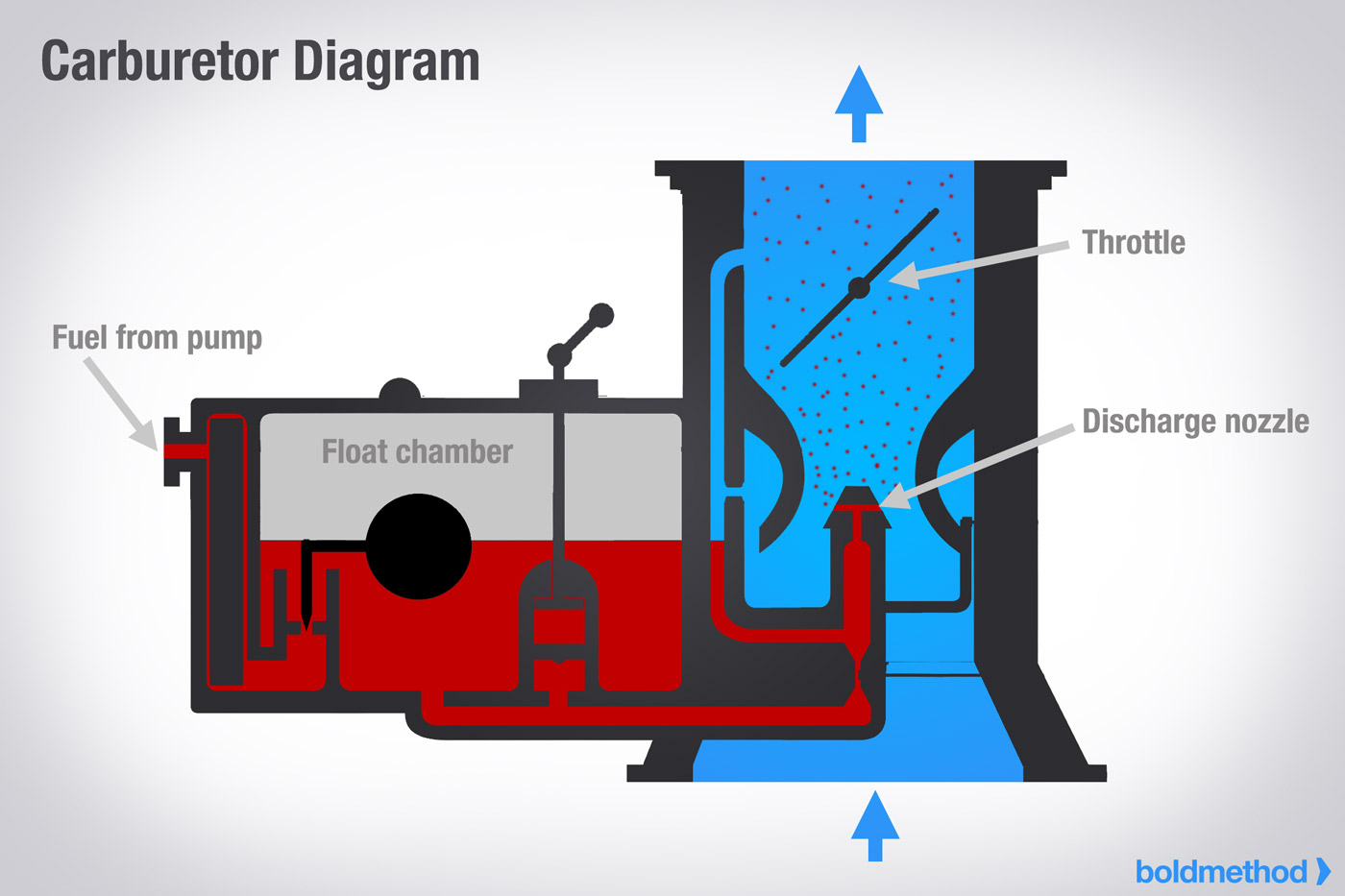
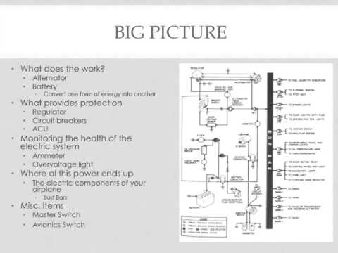
Cessna 172 alternator wiring diagram wiring diagram is a simplified agreeable pictorial representation of an electrical circuit. Thanks for the response i was having some issues understanding the cessna poh diagram so im saving this in onenote. Until the early 90s wire was insulated with pvc but it has since been phased out and replaced with tefzel. Trouble shooting the alternator system. It shows the components of the circuit as simplified shapes and the skill and signal connections along with the devices.
Gallery of Cessna 172 Alternator Wiring Diagram