If the result is not as specified replace the relay. The relay contacts will activate whenever any interconnected alarm.

Brk Electronic Ul217 Csa6 19 Ulcs 530 Ulcs 531 User Manual
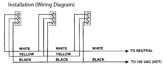
Brk relay wiring diagram. 120v ac smart relay when connected to brk or first alert alarms this relay is designed to activate an auxiliary device like a bell siren strobe light exhaust fan door closer etc. Wiring diagram inspection procedure notice. If wiring the relay remote from the alarm use a maximum of 1000 feet 300 meters of 18awg or larger wire rated at least 300v alarm relay black wire hot black wire white wire neutral white wire orange wire interconnect orange wire danger. To install this relay to an alarm connect the power wires as listed below. Measure the resistance of the relay. Alarm connection relay black wire hot black wire white wire neutral white wire.
It is necessary to register an id code after replacing the tire pressure monitor valve. If wiring the relay remote from the alarm use a maximum of 1000 feet 300 meters of 18awg or larger wire rated at least 300v. Alarm relay black wire hot black wire white wire neutral white wire orange wire interconnect gray wire. Relay is intended for use with brk electronics models 4120sb 4120b 4120 4919 5919 5919th and first alert models sa4121b sa4120 and sa4919b. When alarm is sounded. See diagram for connections.
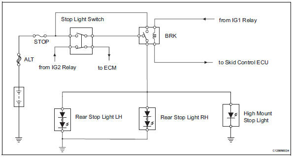
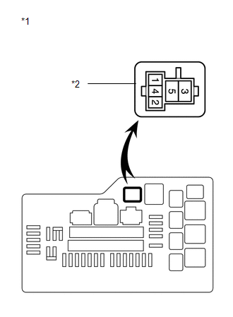
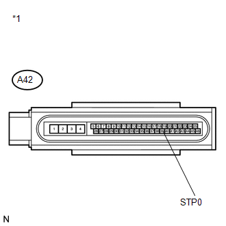
To install this relay to an alarm connect the power wires as listed below. If wiring the relay remote from the detector use a maximum of 1000 feet of 18awg or larger wire rated at least 300v. Remove the brk relay from the engine room no. To install this relay to a brk ac smoke or carbon monoxide alarm connect the power wires as listed below. Fog light relay.
Gallery of Brk Relay Wiring Diagram