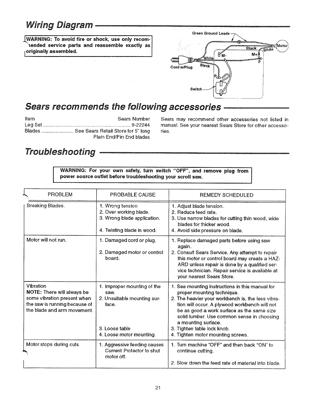
This rectifieris used on smallmotors if no specialrequirementsare needed with respectto the release reaction times of the brake. See the specific system wiring diagram for the balance of the wiring connections required.

British General Analogue 24hr Timer Consumer Unit Module
Bg cuts1 wiring diagram. 8102010 71627 pm. It is din rail mountable and changes 240v ac power into either 8 12 or 24v dc providing constant power to the mains powered door bell. Suitable for bg 46 electric bass guitar kits precision bass pick up to 1 volume 1 tone. Luceco plc luceco distribution centre stafford park 1 telford shropshire tf3 3bd. This bell transformer is part of the bg range of control devices and is suitable for use within any bg metal or insulated consumer unit and any enclosure. Bg offers a variety of circuit protection solutions that will help the designer and installer to comply and meet these new regulations.
Jolin zhu created date. Please note that any use of the sf155b st ation with systems other than the nc1 10a. 3 before mounting the station pull all necessary wiring through the backbox and optional bg tr. The pull station backplate is molded with. 5 carefully arrange the wiring to lie along the edges of the product or box keeping the central area clear. Bg electrical ltd stafford park 1 telford shropshire.
Bg 46 guitar bass twin neck diagram. Twin neck 12 6 string 4 humbuckers and 3 way switch. Suitable for agd 612 double neck. The bg brake rectifier standard for frame sizes up to 100 not available on frame sizes above 100 the brake rectifier bg is a half wave rectifier with overvoltage protection. All mobile equipment up to 32a used outdoors. Description product inner box each inner individual box outer box outer inner box box outer box packaging type pack quantity barcode.
6 to assist with the correct installation please consult the appropriate wiring diagram on this leaflet. The following areas require additional protection by an rcd not exceeding 30ma i socket outlets section 41133 all sockets up to 20a. 4 remove the correct amount of wire insulation. 7 when connecting the new accessory ensure that only the bare end of the wire enters the terminal and no bare wires are visible. Wiring instructions for the bg 12 bg 12l and bg 12lsp 1 if semi flush mounting proceed to step 4. After wiring switch refit front support onto rear box using fixing screws do not overtighten.
Uk sales enquiries 44 01952 238 100. Observe all local and national electrical and building codes. Line diagrams wp12 wp30 wp14 wp42 91 67 1 9 44 4 4 91 67 1 9 44 4 4 91 67 1 9 44 4 4 cat no. 2 mount the backbox before wiring to the pull station. Wiring connections and terminals may not be in the same order as they appear on the equipment.
Gallery of Bg Cuts1 Wiring Diagram