Variety of cummins transfer switch wiring diagram. Verify the method of wiring with your transfer switch and generator before installation.

Industrial Transfer Switch Wiring Diagrams Swichw 2002
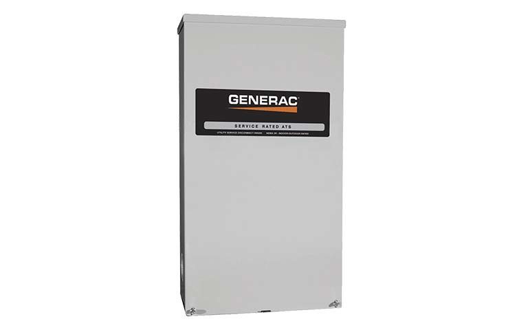
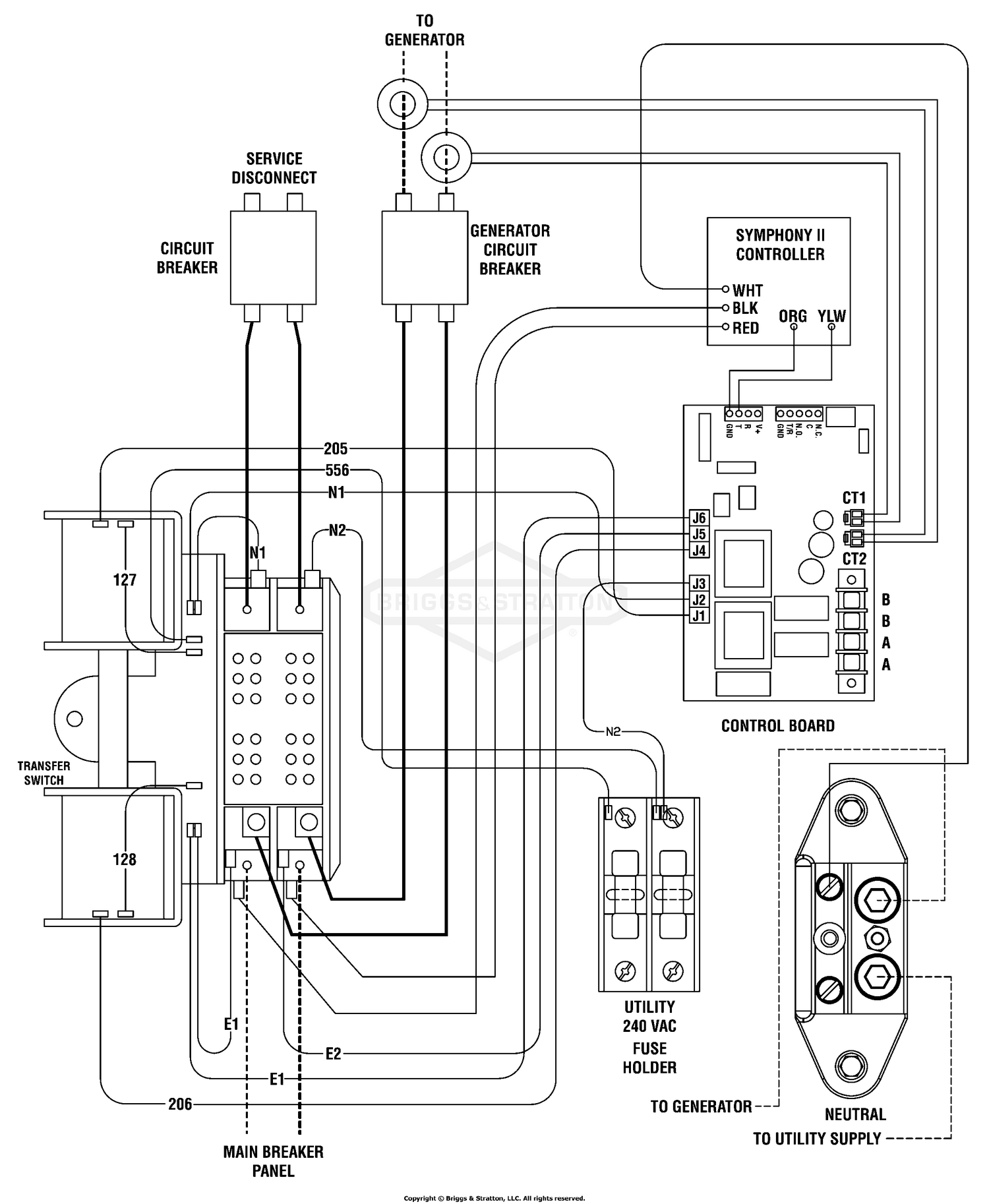
Ats switch wiring diagram. Refer to the smm ownersinstallation manual forvariety of generac amp automatic transfer switch wiring diagram. A wiring diagram usually provides info concerning the relative position as well as setup of tools as well as terminals on the devices to assist in structure or servicing the tool. It reveals the elements of the circuit as simplified forms and the power as well as signal links between the tools. Assortment of generac 200 amp automatic transfer switch wiring diagram. Wiring diagram asco series 300 group g automatic service entrance transfer switch atsntsaus 30 230 amps frame d thr. Variety of ats wiring diagram for standby generator.
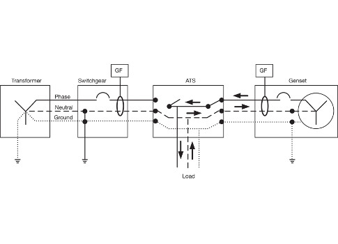
Testing diesel gen sets to iso8528. Technical information 3 standard diagrams transfer between 2 sources 1 bus bar comut 041 a load g s1 g s2 p1 p2 standard solution comut 042 a load s1 s2 q1 q2 ats socomec solution. A wiring diagram is a simplified conventional photographic depiction of an electric circuit. Series 175 surge protective device. Monitoring engine start signals. A wiring diagram is a simplified conventional photographic representation of an electric circuit.
Load bank series numbers explained. Many systems do not switch the neutral wire and tie the three neutral wires together. 7000 series medium voltage transfer switches. The drawings also show the switching of the neutral wire white. Asco sigma wireless gateway simplifies load bank. Amp service entrancenon service entrance automatic transfer switch owners manual.
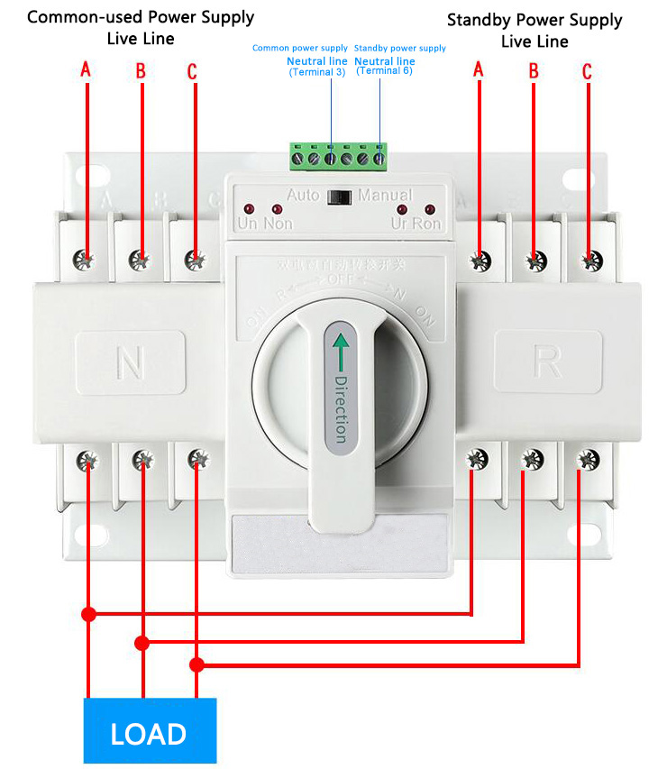
Mar 3 2016 automatic transferred switch ats circuit diagram electrical engineering blog. September 11 2018 by larry a. Figure 4 wiring diagram of a manual transfer switch in the off position. It shows the elements of the circuit as streamlined shapes as well as the power and also signal links between the gadgets. A wiring diagram is a simplified conventional photographic depiction of an electric circuit. All the wiring connections are same as above for manual operation of three phase changeover switch but the switching operation is automatic.
Click on picture for larger view. It reveals the elements of the circuit as streamlined forms and also the power and signal links between the devices. Fig 5 shows 4 poles 3 phase automatic transfer switch ats connection to the main distribution board. Motorised switch cl ncl g q1 q2 ats automatic transfer switch protection arent shown on the following schemes summary. A wiring diagram is a simplified standard pictorial depiction of an electrical circuit. 7000 series transfer switch.
Wiring diagramschematic a v drawing no.
Gallery of Ats Switch Wiring Diagram