Wiring diagram for connection to ariston unvented cylinder boiler electrical supply cable remove internal time clock plug t6360b from the the pcb. 61 wiring diagram for two heating zones 62 wiring diagram for connection to ariston unvented cylinderl.

Ariston Microgenus He Combi Boiler Fault A01 Faulty Pcb
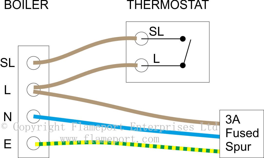
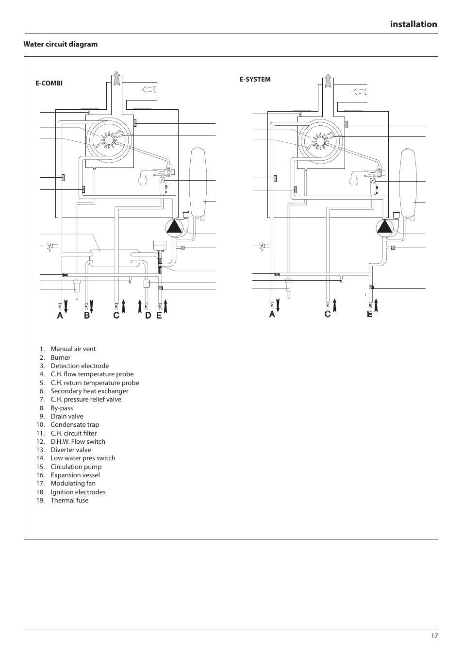
Ariston boiler wiring diagram. Installation electrical diagram for increased safety ask a qualified technician to perform a thorough check of the electrical system. Gas adjustments gas adjustment table 41. 211 electricalsystem diagrams 212 water circuit diagrams 3. It should be kept. It should be kept. B023 3 this manual is an integral and essential part of the product.
61 wiring diagram for two heating zones 62 wiring diagram for connection to ariston unvented cylinderl. B023 3 this manual is an integral and essential part of the product. Wiring diagram for connection to ariston unvented cylinder brown boiler electrical supply cable blue grey orange remove internal time clock plug from the the pcb. Aristons only obligation under the guarantee will be to repair or replace we guarantee that your boiler is a reliable and the faulty appliance at aristons discretion. Thank you for choosing an ariston boiler. The boiler must be installed on a solid permanent wall to prevent access.
Commissioning 31 initial preparation 32 removing the casing 33 control panel 34 initial start up 35 operational adjustments 36 combustion analysis 37 fume discharge monitoring 38 boiler safety systems 39 draining the system 4. Then connect typical room room stat terminal block on the thermostat junction box reverse of the boiler control panel brown see section 210 to 9 10 on. Then connect boiler electrical supply cable greenyellow typical room stat terminal block on the junction box. The boiler must be installed on a solid permanent wall to prevent access.
Gallery of Ariston Boiler Wiring Diagram