Each component ought to be placed and linked to other parts in specific way. Available in 12v ckma12 or 24v ckma24 models.

26a26a Arb Air Locker Wiring Diagram Wiring Library
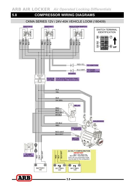
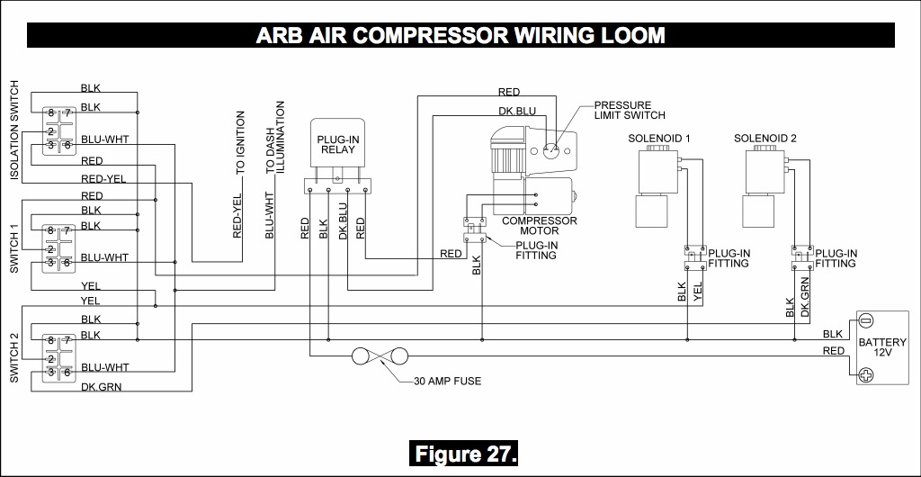
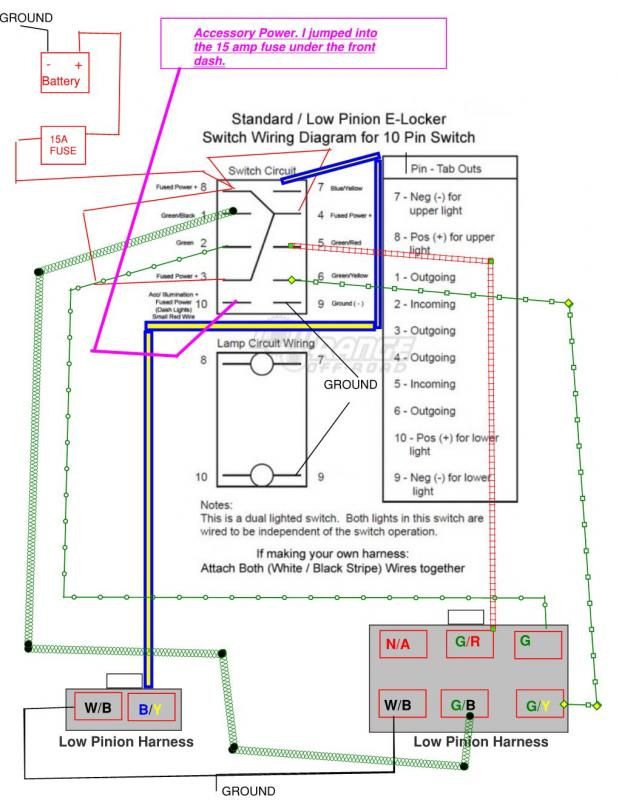
Arb locker wiring diagram. A 12 volt air compressor 24 volt also available engages the unit in approximately 1 second and can be engaged at any vehicle. Otherwise the structure wont work as it ought to be. Arb air locker air operated locking differentials arb air locker air activation system. If you look at the arb wiring diagram the power comes into the middle of the compressor switch red wire w yellow stripe and out right below it red that wire ts and sends power to the pressure switch to arm the compressor and then to the middle terminal of the rear switch. Carling switch wiring diagram arb carling switch wiring diagram carling dpdt rocker switch wiring diagram carling hazard switch wiring diagram every electrical arrangement is composed of various distinct components. For the wiring loom to follow.
The compressor should not be mounted in a position where the running sound might be considered startling or irritating for vehicle occupants. On command lockers the arb air locker is a unique air operated unit for which the locking action is controlled by the driver with a push of a button inside the cab. Longer power wires more inline resistance less air flow rate. Arb air locker wiring diagrams. The arb ckma12 and ckma24 compressor kits were designed specifically as a versatile quick installing compact yet high flow air source to suit the arb air locker which also suits the harsh and demanding environment of the arb air locker user. Arb air locker.
Arb air locker air operated locking differentials 58 58 compressor wiring diagrams ckma series 12v 24v 40a vehicle loom 180409 switch terminal identification.
Gallery of Arb Locker Wiring Diagram