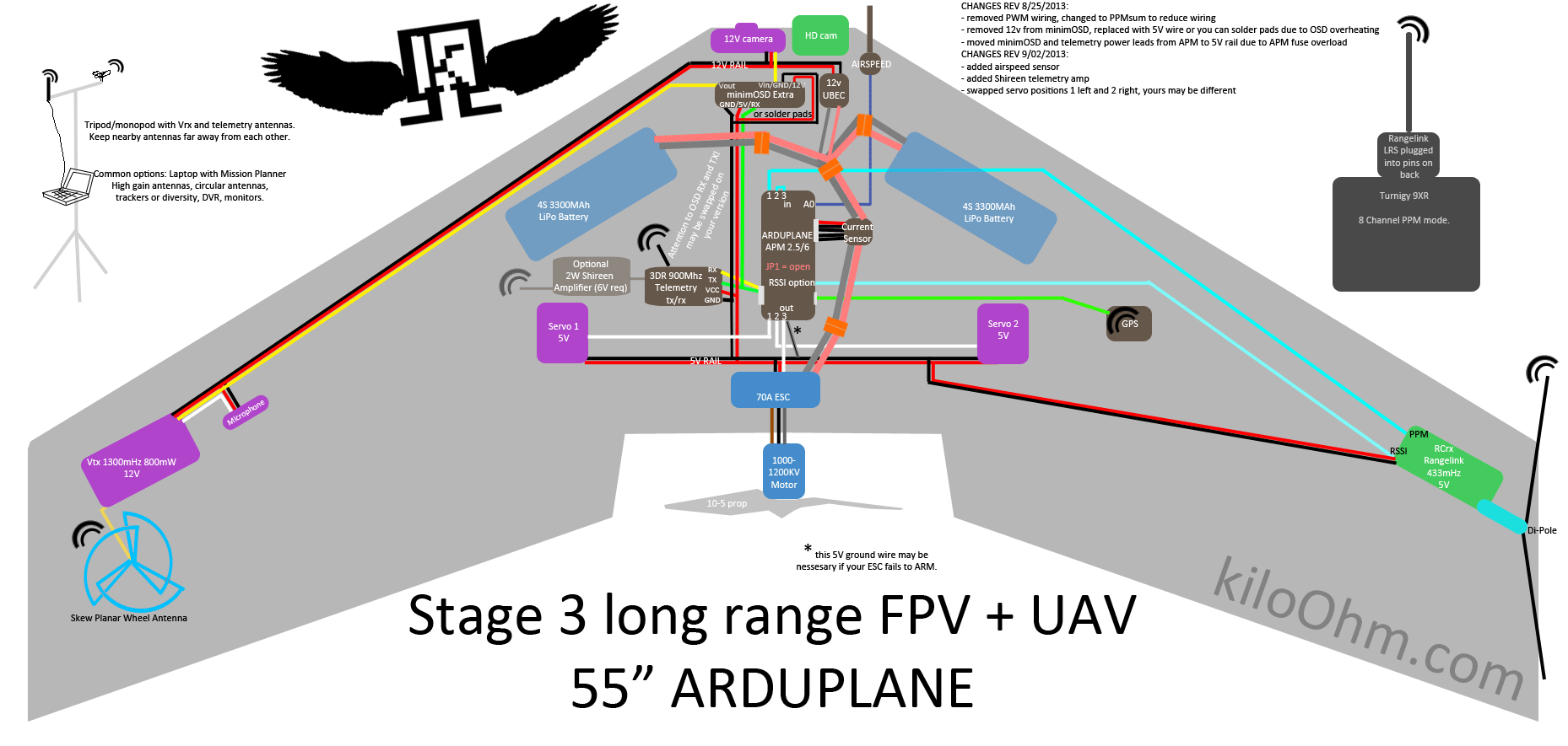
All is mounted on the skywalker. It shows the components of the circuit as simplified shapes and the capacity and signal associates amongst the devices.

9ded70 John Deere Model 710 Manuals Manual Book And Wiring
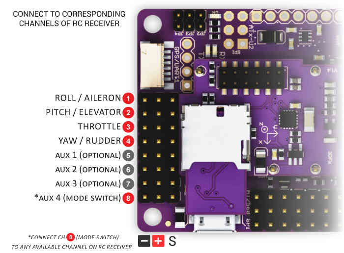
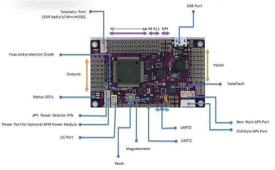
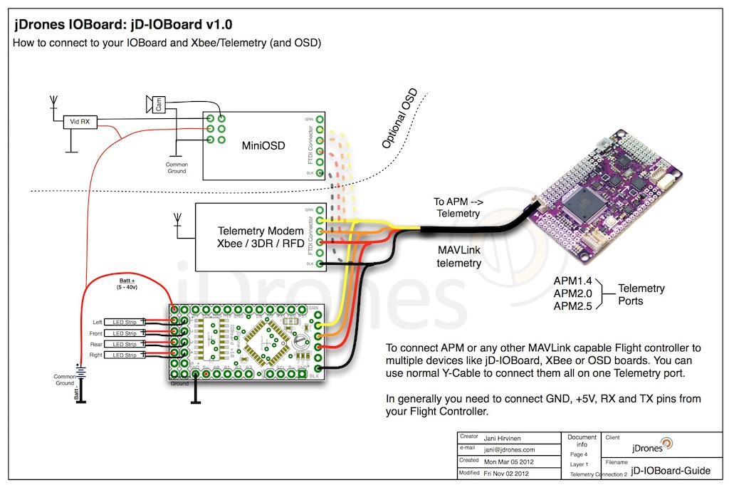
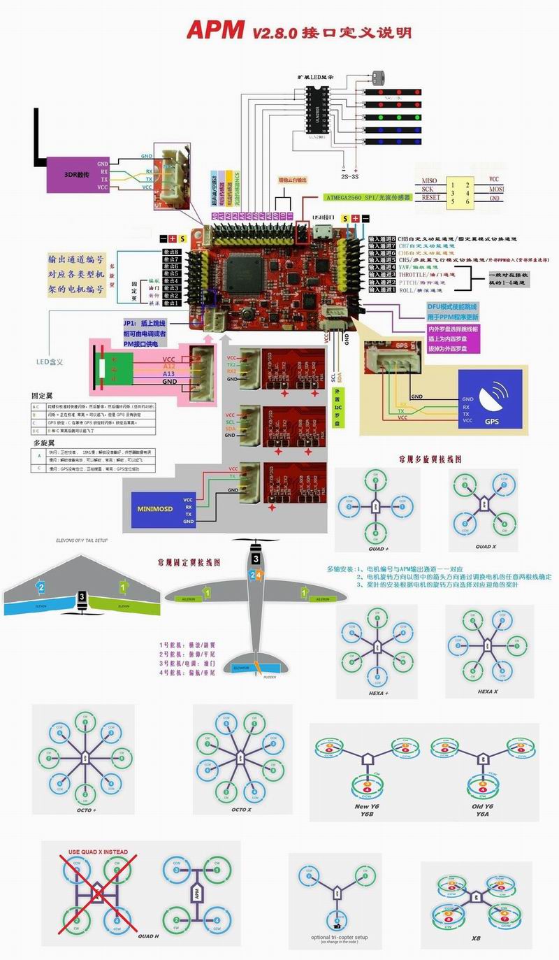
Apm wiring diagram. Connect the gps to the apm i2c port using the 4 position cable. The gps should be plugged in to the i2c port if the apm and telemetry or osd is plugged into the telemetry port on the bottom of the board. Main supply connect electrical wiring from each purge point solenoid to voltage fluctuations should not to exceed. Apm wiring diagram wiring diagram is a simplified okay pictorial representation of an electrical circuit. Credits to this man. The diagram below is an overview of how an apm2 can be connected to a receiver esc gps and even a camera gimbal.
If you wish not to use an apm power module you can use the supplied cable to steal power off the esc bec output rails on the custom breadboard. One 4 position cable and one 5 position to 6 position cable. 3dr gps ublox with onboard compass includes two connector cables. Carefully study the wiring the standard electrical requirement for the apm is 115v diagram below figure 5 to avoid electrical short circuits. Auto pilot rc drone ardupilot apm ardupilot apm connect the ardupilot apm to the computer via usb cable. Montick is supplied with a wiring harness outputs connected on the top connector as indicated below and inputs connected on the bottom connector.
The diagram below is an overview of how an apm2 can be connected to a to apm output signal pins with the m1 wire connecting to the signal pin labeled 1. You still need an esc example wiring diagram for a bixler plane with apm. Reviewing wiring schematic and hook up wires for the ardupilot mega 26 to the ezuhf receiver. Connections between rc receiver and ardupilot mega v2 board this can be dune by cutting the red wire on all but one of the escs or by using a specialjan 20. To connect the gps module to apm 26 connect the gps to the apm gps port using the 5 position to 6 position cable. Apm wiring diagram bmw wiring diagram wiring diagram technic.
Also the diagram is different reference figure b3. For the apm303 sdmo controller we supply quick splice connectors figure 2 so that the montick harness can be connected to the apm303 harness without unscrewing connector blocks. For apm you can use the supplied apm power module for the power. We make extension cables for the 3dr telemetry radio and minumosd. Also available is 230v 5060 hz.
Gallery of Apm Wiring Diagram