Repair parts for the internal wiring harness and for wiring harness components attached to the shift selector will be available through the allison transmission parts distribution center pdc. 1994 holiday rambler alumalite allison six speed push button pad has no power.
85c9 Tcm Wiring Diagram Wiring Resources
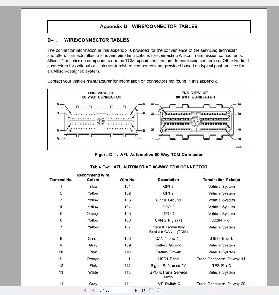
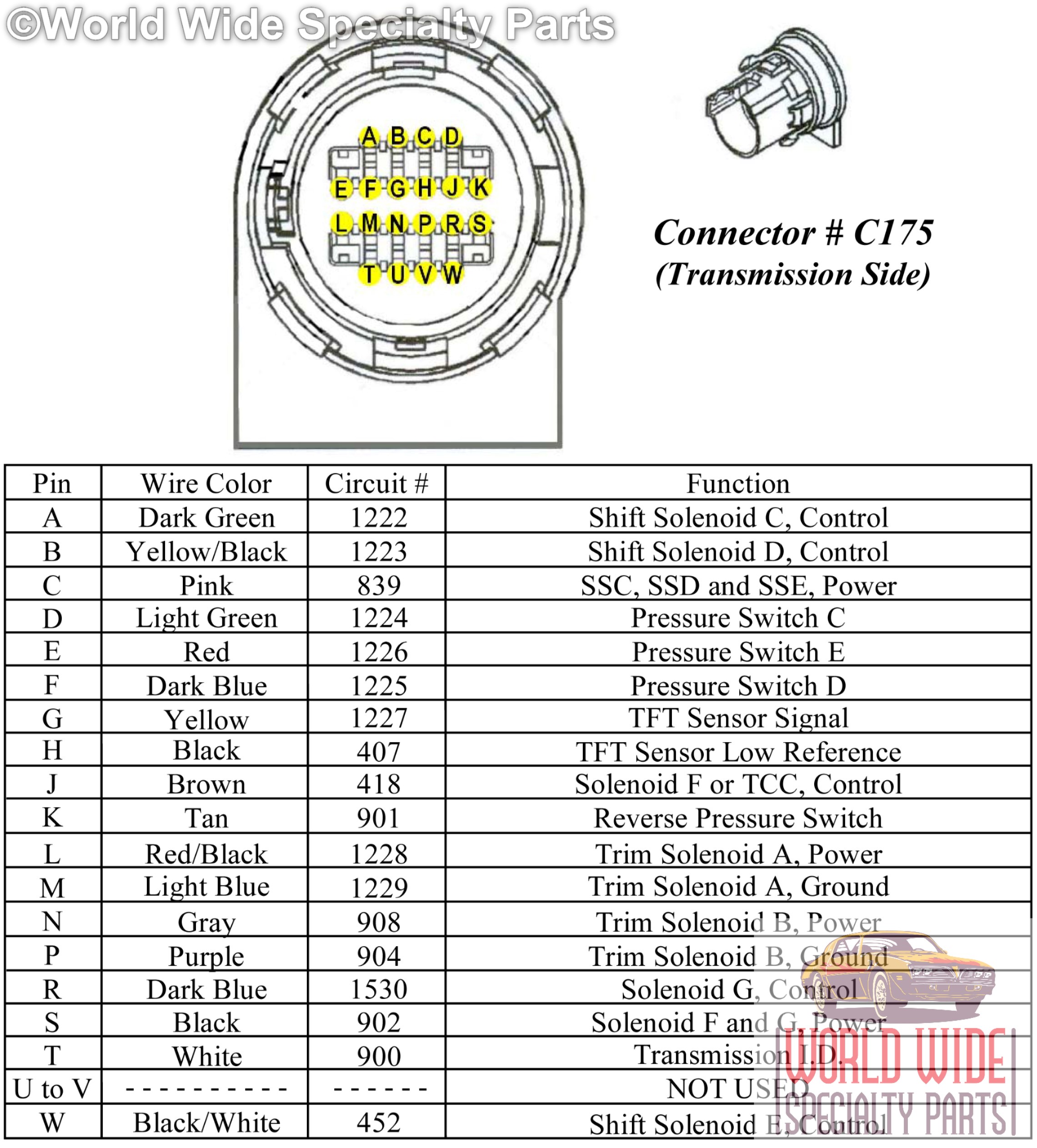
Allison tcm wiring diagram. Dave shares his fool proof method for identifying allison transmission wiring harnesses. Allison transmission at is responsible for warranty on these parts. Allison world 100020002400 gen4 transmission wiring harness parts catalog wt3 drawing detail shifter. Remote 12v or 1224v max feature sealed transmission control module tcm. Use the pn from your appropriate parts catalog or from appendix e in this manual. What color wire goes to the drive button and can i just put a jumper wire so i can move the motorhome a couple miles.
Check the wiring to the tcm first. Allison 2400 series transmission wiring diagram. Use these diagrams to communicate harness design requirements to st clair. These diagrams can also be used to locate the name of a particular connector by its location on the wiring harness. System data march 5 2015 page 5 control module configuration 12 volt 24 volt control module model designations a50 a51 a52 a53 a54 a53 parameter value value units temperature limits 10002000 3000 10002000 3000. Allison transmission 1000 wiring diagram.
Allison transmission 3000 and 4000 wiring diagram wiring diagram is a simplified satisfactory pictorial representation of an electrical circuit. Simply copy the required pages fill in the necessary information and fax to us. Ignition power with the key on ignition power from the key switch 24 is delivered through circuit 13j to absallison connector 377 through circuit 13j to 10 amp fuse 3039 pins 1 2 through circuit 13m and 13mf to tcmcab connector 3034 through circuit 13mf splitting to circuits 102 104 to grey tcm connector 3031 pins 4 2. Utilization of body builder connectors ordered and provided by mack is strongly recommended as your power lighting and ground source for body installation pto installation and operation. A wiring diagram is a simplified standard photographic representation of an electric circuit. Allison 4th generation controls.
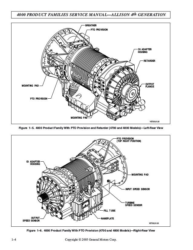
Diagrams for wtec ii iii 100020002400 and gen4 transmissions. Cutting into wiring harnesses is not recommended as it may affect can bus messaging. It shows the components of the circuit as simplified shapes and the power and signal associates in the midst of the devices. Always check the latest information at the wiring diagrams location. Tcm is not lighting up or doing anything. Transmission control module figure 12 shows allison 4 th generation electronic control components.
Allison 4 th generation controls consist of the following elements. It shows the components of the circuit as simplified shapes as well as the power and also signal connections between the tools. Assortment of allison transmission wiring schematic. Wires are good to tcm. Joe saturday 27 june 2020 2115. Figure 11 is a block diagram of the basic system inputs and outputs.
Gallery of Allison Tcm Wiring Diagram