Accuload iii s dimensions mn06135 issuerev. 3ø wiring diagrams 1ø wiring diagrams diagram er9 m 3 1 5 9 3 7 11 low speed high speed u1 v1 w1 w2 u2 v2 tk tk thermal overloads two speed stardelta motor switch m 3 0 10v 20v 415v ac 4 20ma outp uts diagram ic2 m 1 240v ac 0 10v outp ut diagram ic3 m 1 0 10v 4 20ma 240v ac outp uts these diagrams are current at the time of publication.

Smith Meter Model 210 Digital Electro Manualzz
Accuload iii wiring diagram. 13 617 page 14 section iv diagrams figure 4. Related publications lists the literature that is associated. All dc wiring must be routed into accuload iii through the conduit entries located in the bottom of the housing. The aicb board is de signed to either be mounted in the accuload iii housing or in a standalone enclosure. Specifications describes the specifications of the accuload iii s electronic preset. The accuload iii with als1 and ald1 firmware has the capability of handling up to twelve metered injectors twelve meter inputs twelve solenoid valve outputs and twelve additive pump outputs.
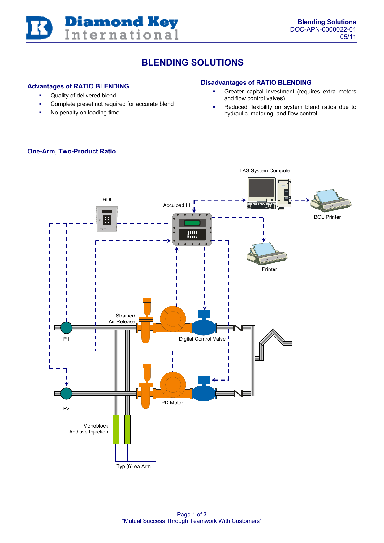
By offering a wide variety of loading arm configurations mixing blend arms with straight product accuload iii maximizes efficiency and product throughput like never before. Wiring between transmitter and accuload should be done with a shielded8 communication protocol the message format is. Technipfmc smith meter accuload iii pdf user manuals. Analog module settings jp1 on eaai. Smith meter accuload iii the accuload iii product line provides the power flexibility and configurability required for todays highly efficient and regulated terminals. Board upgrade wiring changes and additions three permissive inputs smart additive control up to 12 metered injector control 2.
Diagrams covers dimensional outline drawings wiring schematics etc. Considered when installing the accuload iii. Promass 80 83 and 84. View online or download technipfmc smith meter accuload iii installation manual. Accuload iii q dimensions mn06135 issuerev. Wiring terminals 4 20ma and 1 5 vdc inputsoutputs.
One of the accuload iiis. A1 a2 text cr lf for an instruction to accuload iv or a1 a2 text cr lf for a response from accuload iv product 1 6 accuload iv communications manual. Section iv diagrams figure 3. Installation describes the areas that have to be con sidered when installing the accuload iii. The addpak is a specific addition to accommodate. Kdc layout configurable jumper locations are heavily circled on the diagram above.
Wiring diagram prime 4 meter single pulse note. 13 617 page 15 section iv diagrams figure 5. Diagrams covers dimensional outline drawings wiring schematics etc. Do not route dc and ac wiring through the same conduit entry. Accuload iii controls a wide range of types and quantities of additive systems.
Gallery of Accuload Iii Wiring Diagram