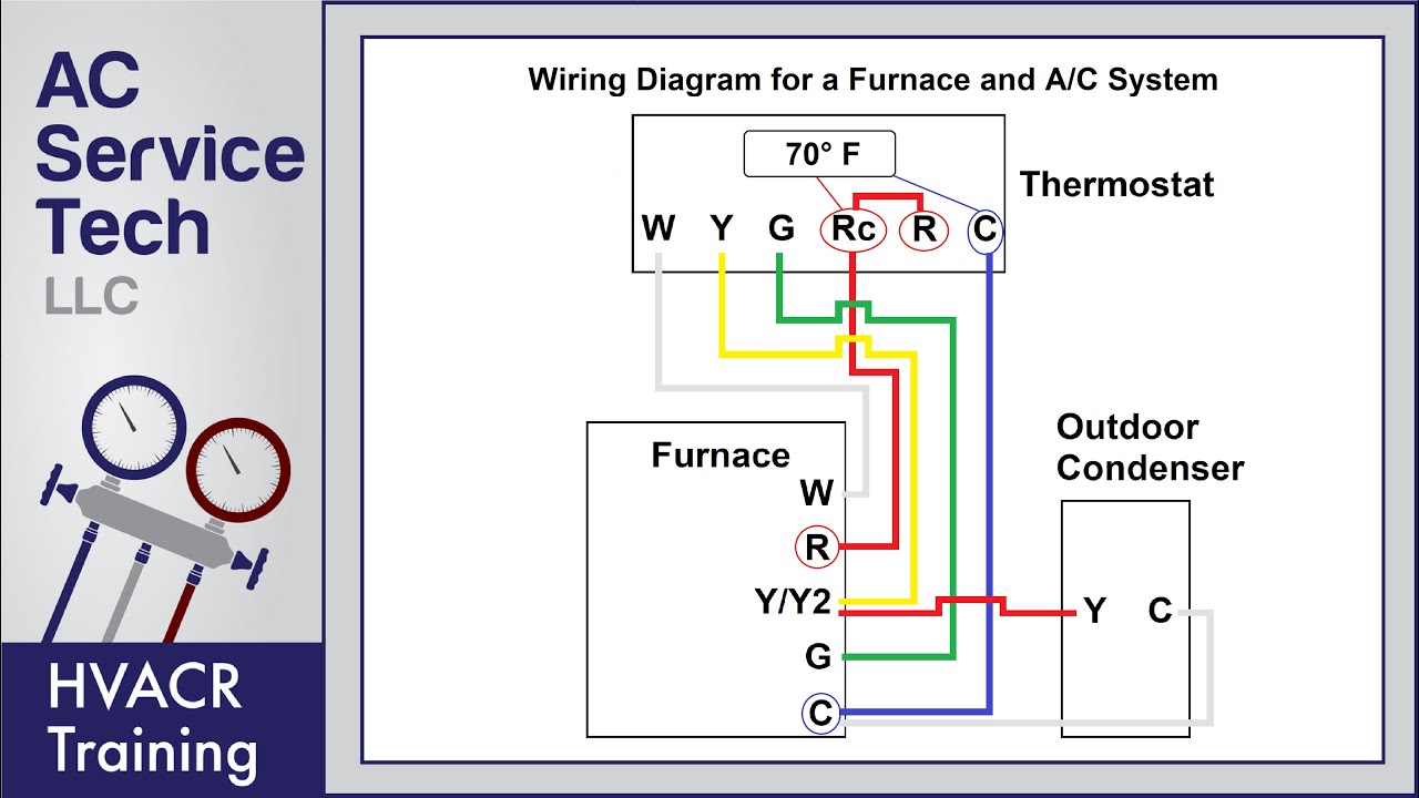
C terminal to the blue wire. Red wire for air conditioner control power hot.

Wo 5522 04 International 4300 Wiring Diagram Free Diagram
Ac wiring diagram. G terminal to the green wire. It reveals the components of the circuit as simplified shapes and the power and also signal links in between the devices. Always refer to your thermostat or equipment installation guides to verify proper wiring. When and how you can make use of a wiring diagram. This diagram is to be used as reference for the low voltage control wiring of your heating and ac system. When wiring to supply power you are creating an electrical circuit.
It shows just how the electric cords are adjoined and can additionally show where fixtures and elements might be linked to the system. August 24 2018 by larry a. Breakdown of colors and terminals thermostat wiring diagram for ac unit. A wiring diagram is a streamlined traditional pictorial representation of an electric circuit. Y terminal to the yellow wire. A wiring diagram is a simple graph of the physical connections and also physical design of an electric system or circuit.
The ground wire is meant to dispel any extra charge using the earth as the dispeller. 3 types of electrical wiring diagrams for air conditioning systems there are three basic types of wiring diagrams used in the hvacr industry today which are. How to wire an air conditioner for control 5 wires. Electricity flows through the hot wire to a device or power receptacle and back through the neutral wire. Notesome ac systems will have a blue wire with a pink stripe in place of the yellow or y wire. Wellborn collection of goodman ac unit wiring diagram.
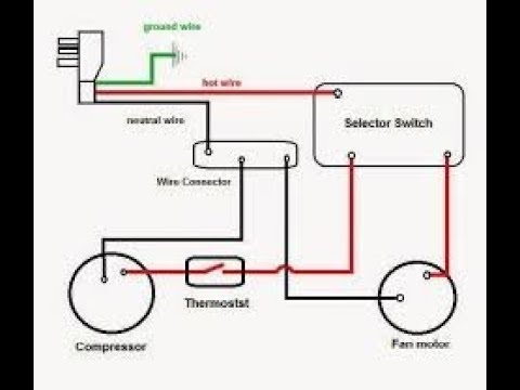
R terminal for the red wire. Notesome ac systems will have a blue wire with a pink stripe in place of the yellow or y wire. Window air conditioning unit electrical wiring diagrams touch and remote control type 14 the power flow inside a typical window air conditioning unit in the cooling mode when you turn the selector switch to cool mode the power that came in from the cord that connected to the selector via hot wire goes to the fan so the fan operates. A continuous circuit consists of a hot wire a neutral wire and a ground. Always refer to your thermostat or equipment installation guides to verify proper wiring. W terminal to the white wire.
This diagram is to be used as reference for the low voltage control wiring of your heating and ac system.
Gallery of Ac Wiring Diagram