Hager rccb wiring diagram hager residual circuit breaker rccb elcb 63amp 4 pole 100ma hager rccb wiring diagram wiring diagram is a simplified enjoyable pictorial representation of an electrical circuit. It reveals the elements of the circuit as streamlined shapes and the power and signal links between the gadgets.

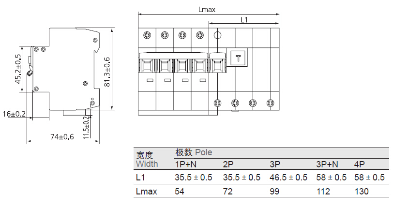
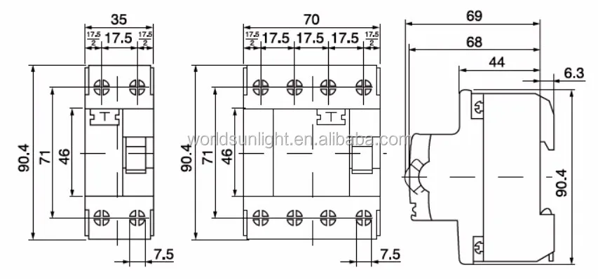
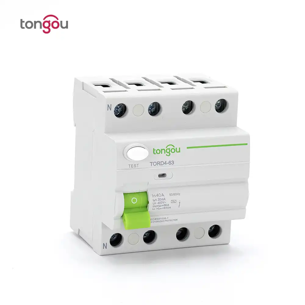
Rccb Technical Data
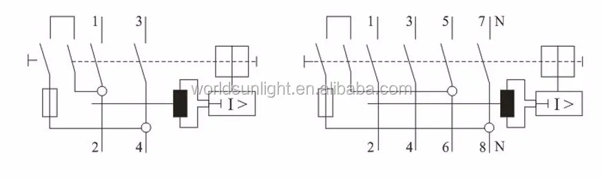
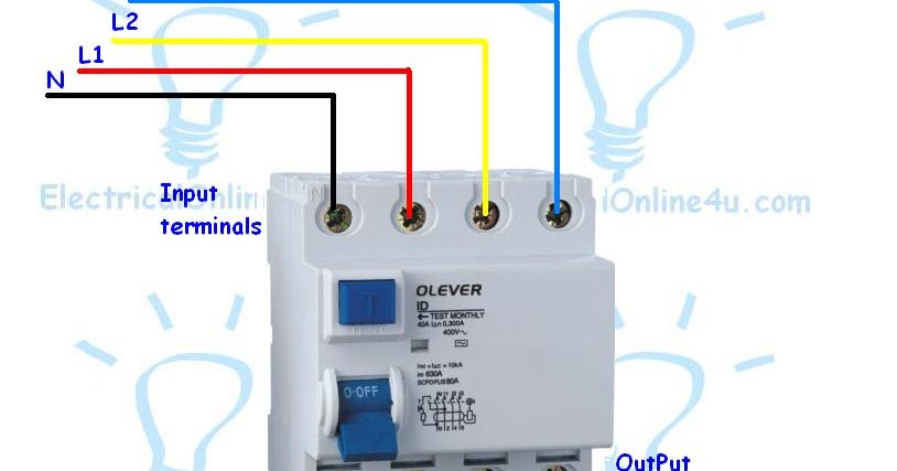
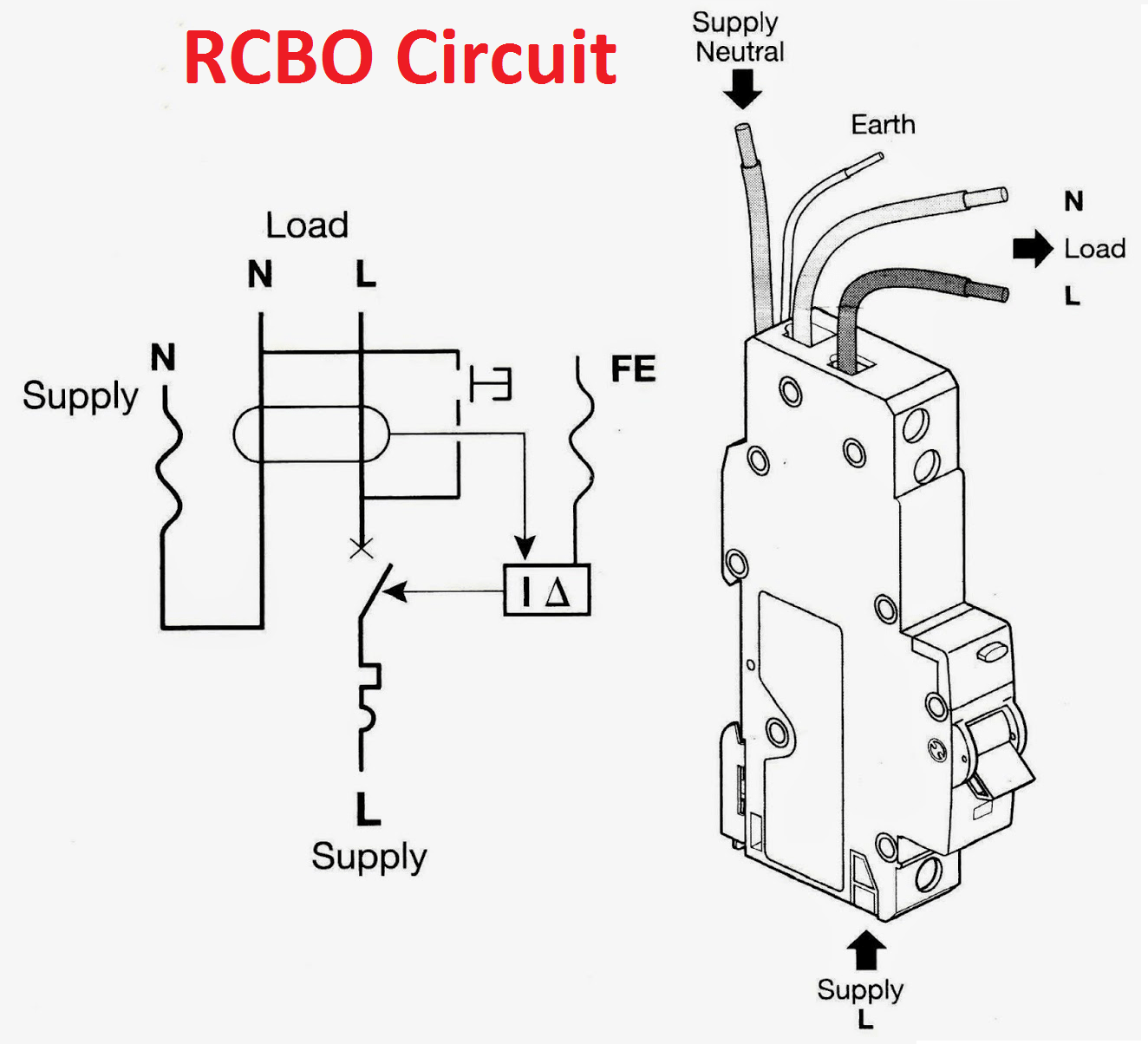
4 pole rcbo wiring diagram. Collection of 4 pole starter solenoid wiring diagram. More electrical tips and diagrams wwwaboutelectricitycouk like subscribe and dont skip the ads shopping list. A wiring diagram is a streamlined conventional pictorial representation of an electrical circuit. How to wire rcbo in consumer unit uk. I could not find wiring diagram for these online. Where 4 pole devices are used as 2 pole devices connect active and neutral conductors as shown on wiring diagram on the rcd for test button to operate.
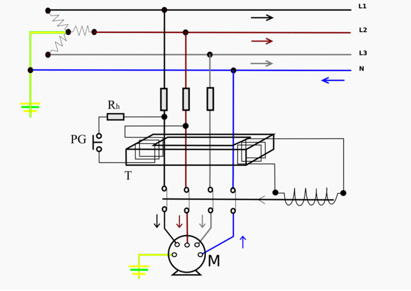
Single pole rcbo problems. Google rcd for more on how leakage is detected. 4 pole 35 mm jack wiring diagram 35 mm stereo jack wiring diagram 4 pole 4 pin 35 mm jack wiring diagram 4 pole 35 mm jack wiring diagram every electrical arrangement consists of various different pieces. By lazyboy in forum. Rcbo rcbo is a residual current operated circuit breaker with integral overcurrent protection. Otherwise the arrangement wont function as it should be.
4 description module width catalogue no. Rcbo wiring has both active and neutral so that it can detect leakage current. 4 6 8n 3 7n to unprotected circuits to rcd protected circuits n a n a n a a n e a ol main neutral link n a to unprotected circuits n a to rcd protected circuit to unprotected circuits 5. It shows the components of the circuit as simplified shapes and the capability and signal connections in the midst of the devices. Senior member join date jul 2011 location wa posts 135. Wiring a four poles rcbo or gfci circuit breaker three phase rccb wiring the three phase wiring for gfci or rcd rccb or rcbo wiring diagram shows the three lines l1 l2 and l3 and neutral has been connected as input to the rccb from main board followed by mcb ie.
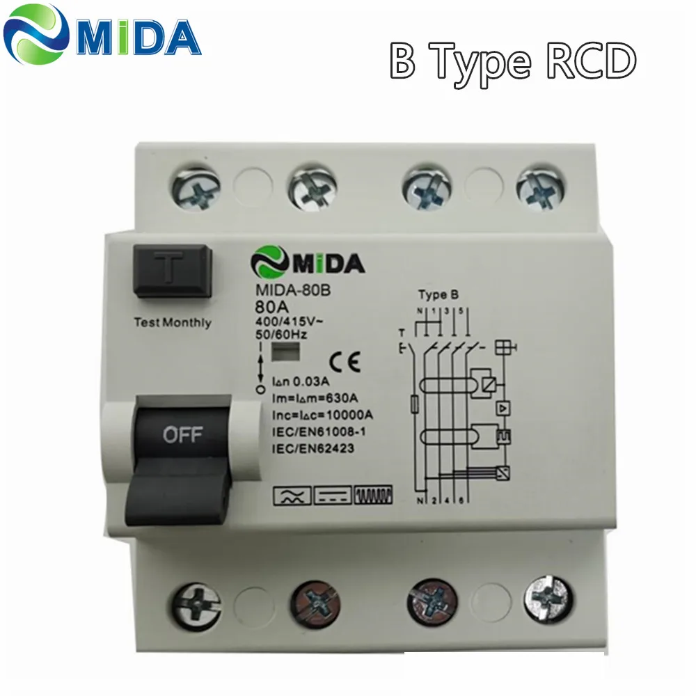
Rcbo 6 ka 1 p 10 a 30 ma mod6 1 mod6 rcbo 1 1030al rcbo 6 ka 1 p 16 a 30 ma mod6 1 mod6 rcbo 1 1630al rcbo 6 ka 1 p 20 a 30 ma mod6 1 mod6 rcbo 1 2030al rcbo 6 ka 1 p 25 a 30 ma mod6 1 mod6 rcbo 1 2530al rcbo 6 ka 1 p 32 a 30 ma mod6 1 mod6 rcbo 1 3230al mod6 rcbo 1 m6pb36m160 1 pole rcbo features. If you use 3 phase 4 wire system supply then instill a 4 pole rcd in your main distribution board fuse box for safety. A mechanical switching device designed to make carry and break currents under normal service conditions and to cause the opening of the contacts when the residual current attains a given value under specified conditions. Each part should be set and linked to different parts in specific way. V v v. The above image diagram is just an example and rcd is available in many shapes and types however you can use this method in wiring an 4 pole rcd.
12th aug 2013 1209 pm 2.
Gallery of 4 Pole Rcbo Wiring Diagram