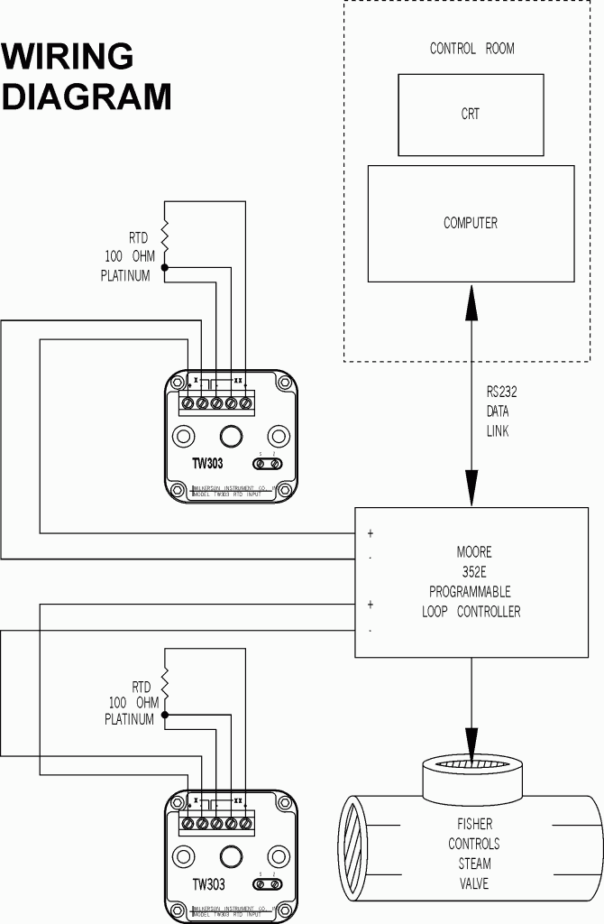
2 wire rtd wiring diagram. As long as the junctions are near the rtd as in a connection head errors are negligible.
3 Wire Rtd Sensor Wiring A 3 Wire Rtd 3 Wire Rtd Probe
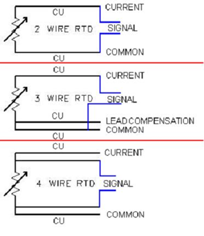
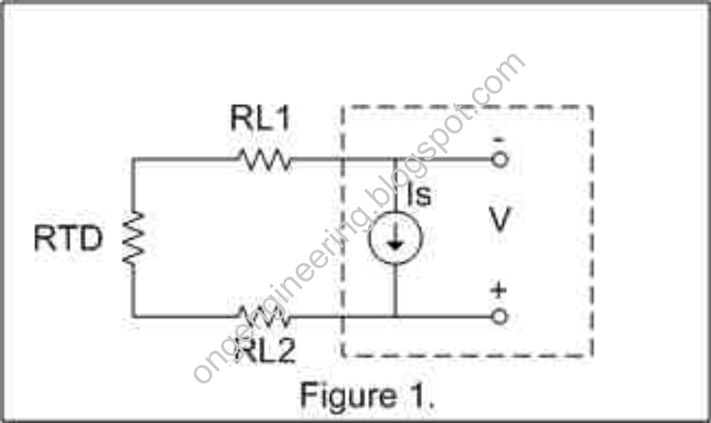
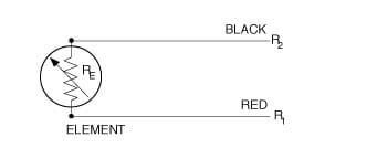
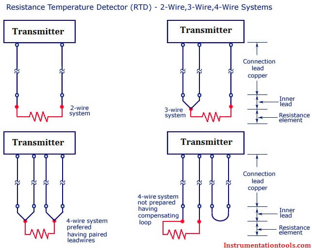
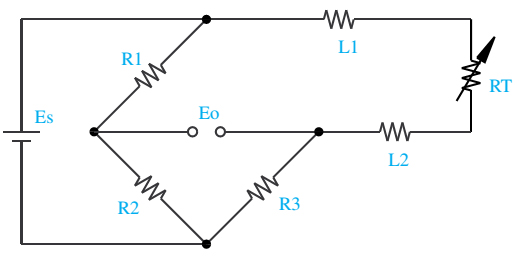
2 wire rtd wiring diagram. Es is the supply voltage. A 2 wire configuration with a compensating loop is also an option. Rtd wiring configurations there are three types of wire configurations 2 wire 3 wire and 4 wire that are commonly used in rtd sensing circuits. Rtd pt100 3 wire wiring diagram gallery rtd sensors 2 3 4 wire rtd sensors resistance temperature detectors. There are three different rtd configurations supported by the sen 302012 breakout boards as well as two different type options available. 2 wire rtd signal connection connect the red lead to the excitation positive.
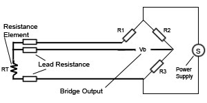
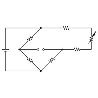
In this uncompensatedcircuit lead resistance l1 and l2 add directly to rt. And rt is the rtd. Sor resistance temperature detector rtd proflow systems. It shows the components of the circuit as streamlined shapes and also the power and also signal links between the gadgets. The board is hard coded for rtd type pt100 vs pt1000 or custom but jumper wires may be used on the input screw terminal block to readily switch between 2 3 and 4 wire rtds for your application. R1 r2 and r3 are fixed resistors.
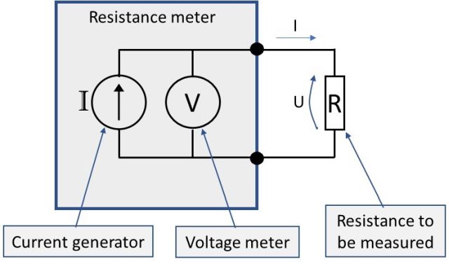
2 wire circuit wired to a 3 wire or a 4 wire circuit. This is the easiest wiring you can just use either terminal block slot on the sides for each wire. Use jumper wires between the excitation positive to the channel positive on the daq deviceconnect the black or white lead to the excitation negative. Shown is a 2 wire rtd connected to a typical wheatstone bridge circuit. Eo is the output voltage. 2 wire rtd connections the 2 wire rtd configuration is the simplest among rtd circuit designs.
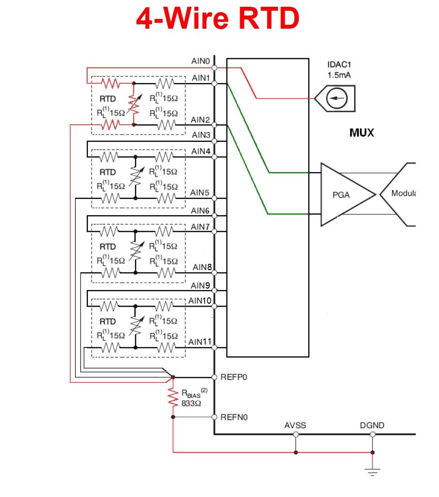
3 wire rtd wiring diagram awesome rtd sensor temperature ppt video. 4 wire rtd wiring diagram collection rtd sensors 2 3 4 wire rtd sensors resistance temperature detectors. 2 wire rtds are mostly used with short lead wires or where close accuracy is not required. Assortment of rtd pt100 3 wire wiring diagram. 2 wire construction is the least accurate of the 3 types since there is no way of eliminating the lead wire resistance from the sensor measurement. If necessary you can connect a 2 wire rtd to a 3 wire circuit or 4 wire circuit as shown.
Then either solder closed the jumpers next to the rtd terminal block or put little wires in the right and left terminal blocks to short them together. 3 wire rtd wiring diagram awesome rtd sensor temperature ppt video. 4 wire rtd wiring diagram. Jumper the excitation negative to the channel negative on the daq device. What is an rtd rtd types uses and more by jms southeast. What is an rtd rtd types uses and more by jms southeast.
A wiring diagram is a streamlined standard photographic depiction of an electrical circuit.
Gallery of 2 Wire Rtd Wiring Diagram

.jpg)