6 uv lamp connection 1. Er uv14 24v uvc lamp installation maintenance instructions when installing and using this electrical equipment basic safety precautions should always be followed including the following.

Uvc Germicidal Replacement Lamps
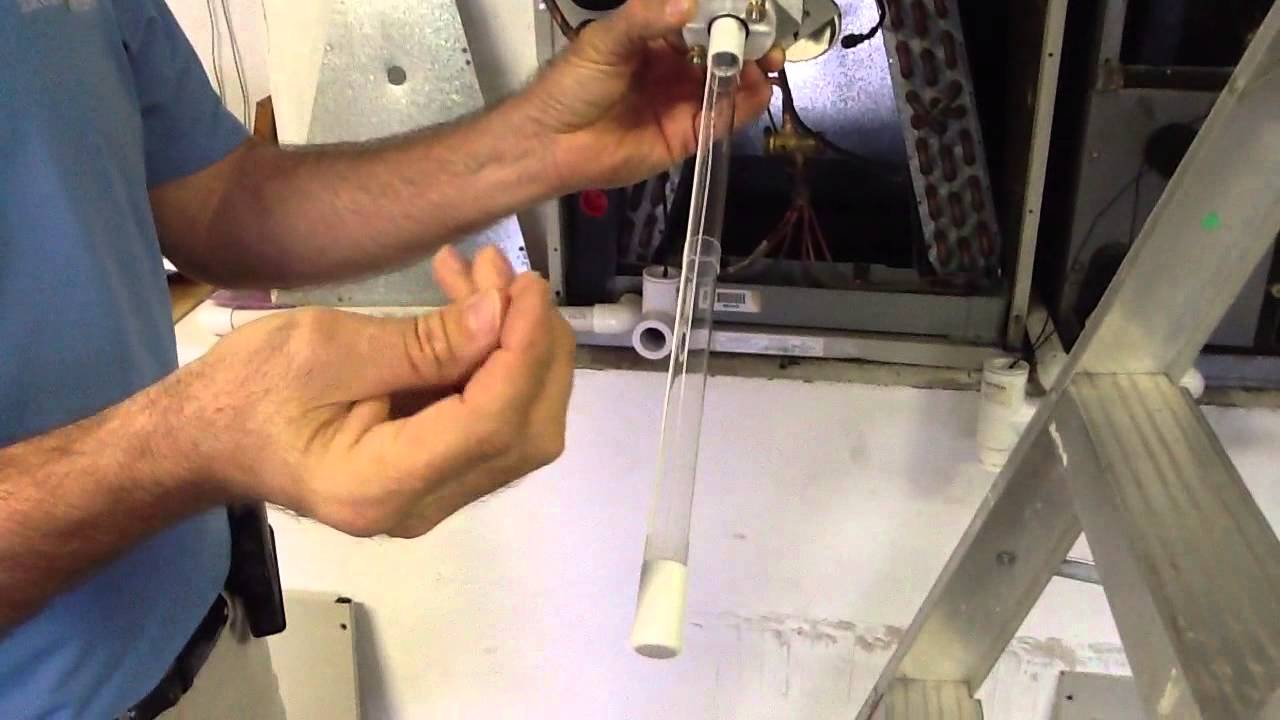
Uvc 24v wiring diagram. When all the other components are properly installed connect the uv lamp cable to the power supply cable. Slightly pull on the wire to ensure it is locked into the terminal. 1read and follow all instructions. The low voltage power supply 18 to 32 vac is marked er. Do not expose wiring or plastic parts to uvc light. Do not install device beneath a humidifier or source of water.
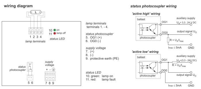
Germicidal ultraviolet uv c applications wiring diagrams view the wiring diagrams for ballasts 10 0091 10 0127 10 0136 10 0137 10 0155 10 0201 10 0210 below or download a pdf ballast specification sheet which includes the ballast specs photos lamp types and wiring diagrams. To remove a wire from the terminal block push in the orange release button below the wire and pull the wire out. Insert a stripped wire into the corresponding hole of the terminal block. Audio wiring diagram 1. Eliminate pollutants from indoor air. 2always be sure the unit is unplugged during installation or service procedures.
This is the datasheet for the uv led which we are using. All the led needs is approximately 33v dropped across it and 16 18ma flowing through it. Germicidal lights use intense rays of ultraviolet light to control and kill contaminants like viruses bacteria yeast and mold. The high voltage 120 to 277 vac power supply is marked st. The datasheet specifies that this led should receive between 3v and 36v of voltage dropped across it. Installed inside the hvac duct system it improves the air in the entire home.
Improves air quality and protects heating and. Light models uvc24v uvc41ws uvc41wd. Use the wiring diagrams below to connect to power. If the uvc device is installed near an air filter check with filter manufacturer for uvc resistance properties.
Gallery of Uvc 24v Wiring Diagram