Users are required to. Typical wiring diagrams description frs21 frs2 frs20 2 nc.
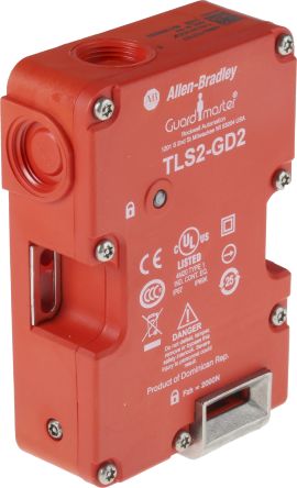
440g T Solenoid Interlock Switch Power To Lock 24 V Ac Dc
Tls2 gd2 wiring diagram. In the wiring diagram the tls3 gd2 interlock is connected to input points 0203. Gd2 standard 440g t27251 440g t27169 440g t27234 ³. Wiring diagrams 8 recommended relays 10 maintenance 10 declaration of conformity 10 important save these instructions for future use target actuator tlszrl gd2 target switch alignment marks. With an 8 pin micro connector not all contacts are connected. Double click the input points 0203 line. Allen bradley alldatasheet datasheet datasheet search site for electronic components and semiconductors integrated circuits diodes triacs and other semiconductors.
To monitor independently the safety contacts and the solenoid feedback tl s 1 2 and 3. Red switches tls1 tls2 tls3 contact configuration jumper between 12 41 jumper between 12 41 and 22 51 contact action. For application and wiring diagrams see safety applications and wiring diagrams. Of pins 8 pin micro m12 2 24v dc 1 aux 7 0v 6 safety b 3 lock command 8 safety a 4 safety b 5 safety a. For special applications the choice of device type is. The tls2 gd2 is generally used in applications where the machine is locked only during the machine cycle and the following is an example schematic.
This is so both contacts are open and closed at the same time and. Tls2 gd2 tls2 gd2 wiring diagram datasheet cross reference circuit and application notes in pdf format. Guard locking interlocks tls1 gd2 datasheet tls1 gd2 circuit tls1 gd2 data sheet. Connection systems description 8 pin micro m12 12 wire. Each type typical wiring diagrams description frs21 frs2 frs20 2 nc. The jumper between 12¼41 m ust be removed.
Two tls2 gd2 interlocks are connected in series to an msr safety relay. See typical wiring diagrams on page 3 45 for wiring details. 2 rockwell automation publication 440g in016a en p october 2017 tlszrl gd2 guard locking switch. The tls 2 gd2 has a power to lock function. In the wiring diagrams that are shown in this publication the type of allen bradley guardmaster device is shown as an example to illustrate the circuit principle. For application and wiring diagrams see page power.
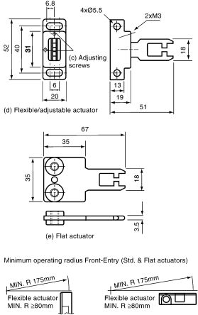
Read this document and the documents listed in the additional resources section about installation configuration and operation of this equipment before you install configure operate or maintain this product. Typical wiring diagrams description color function no. Tls2 gd2 application note page 3 of 4 5 example schematic a the following is an example schematic. 1 2 opto electronics 3 interlock switches 4 5 approximate dimensions dimensions are shown in mm in. The 12 wire cordset 889m f12ah 9must be used and for the tls1 and tls2. Since this is a dual channel circuit with two normally closed contacts set the operation parameter 57 to equivalent.
46 di emd mt gd2 grip enabling switch jog powerflex 70 2 3 d 0 48 di emd tls1 gd2 trojan t15 e stop 100s c 3 4 e 0. Dimensions are not intended to be used for installation purposes.
Gallery of Tls2 Gd2 Wiring Diagram