It reveals the elements of the circuit as streamlined shapes and also the power as well as signal connections in between the devices. From wall and ceiling mount to wall switch and wireless leviton motion sensors enhance.

What Kind Of Switch To Operate And Bypass Motion Sensor
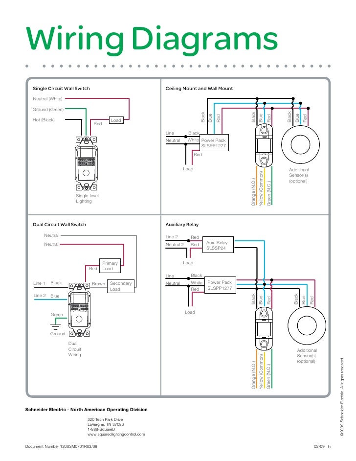
Occupancy sensors lighting wiring diagram. Instruction sheets specification sheets wiring diagrams. Each black wire can be a line or a load. Assortment of lutron occupancy sensor wiring diagram. Lutron occupancy sensor wiring diagram. It shows the parts of the circuit as streamlined forms and the power and also signal links in between the tools. Wiring diagram drawing description.
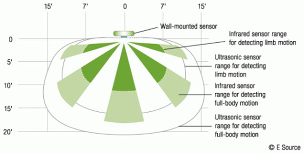
A wiring diagram is a simplified standard photographic representation of an electrical circuit. Building information modeling bim files customer use drawings. Install a 4 way occupancy sensor to replace the existing 4 way switch. Eatons motion sensor lighting controls use advanced passive infrared pir and ultrasonic sensing technology to detect your presence and switch lights on. 2 occupancy sensors can be configured as auto on auto off or manual on auto off. By headcontrolsystem variety of lutron occupancy sensor wiring diagram.
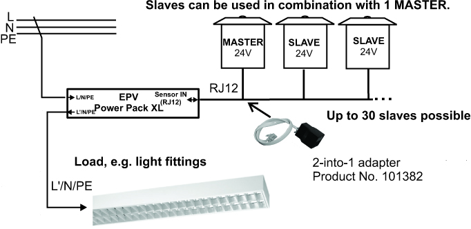
These 3 way occupancy sensor switches may replace the existing 3 way switches. The lighting is controlled by the standard 15 vdc sp20 mv switchpack relay. High bay occupancy sensors and controllers high bay occupancy sensor. The os is powered by the 24vdc sp r 20 120 receptacle switchpack ps 24v. Leviton offers a wide selection of occupancy sensors and vacancy sensors commonly referred to as motion sensors or motion detectors or motion light sensors for commercial and residential applications. Wiring a single lighting load controlled by occupancyconnect.
Wiring a 3way and 4way occupancy sensor. Then once youve left the room our sensors turn the lights off following a preset period of time. A wiring diagram is a simplified conventional photographic depiction of an electric circuit. Maestro sensor 369666f 4 090519 specification submittal page ob name. When motion is detected the blue wire is electronically connected. Wallbox dimming using only low voltage wiring to the switchbox using occupancy sensor for lighting and control.
Sfr 7 the sfr 7 series mini low bay sensor is a compact line voltage occupancy sensor that snaps directly into a small cavity in a fixture. One of the black line wires connects to line voltage from the panel the other black or red load wire connects to the light s. Vacancy sensors are configured as manual on auto off only. These state of the art devices use passive infrared ultrasonic or a combined multi sensing technology. Consider installing 3 way occupancy sensor switches that have a wide angle coverage and variable time delays. Lighting controls sensors.
Hi craig you have asked a great question. Refer to the wiring diagram on the next page for the following procedures. Occupancy sensor switch wires each have two black wires or one black and one red and ground green. Occupancy sensor wiring diagram 1. Enjoy advanced energy savings and state of the art automation with eatons occupancy and vacancy sensors. Switch with occupancy vacancy sensor selection matrix 1 xx in model number represents colorfinish code.
Gallery of Occupancy Sensors Lighting Wiring Diagram