This is the digital forward phase dimming room controllers lmrc 221 lmrc 222. Lmrc 220 series digital room controllers include one or two outputs to control a total of up to 20 amps.

Document Pdf Document
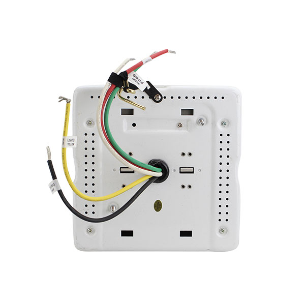
Lmrc 222 wiring diagram. Do dimming not connect different load load types to the same load output. Each relay is rated for up to 20a. In a dlm local network with only lmrc 222 room controllers the lmrc 222 with the highest serial number is the master carrying load 1 and load 2. Page 1 output to dlm local network. The lmrc 222 has two load outputs. Wiring diagram input and output are wago 250 connectors.
The success of a dlm network installation and the functionality of the segment to this device is followed exactly as depicted in the wiring instructions and diagram. Load ratings include incandescent magnetic low voltage forward phase compatible electronic low voltage and led drivers neon and cold cathode and dimmable. Provides low voltage power over cat 5e cable lmrj. Controls lmrc eliminating wiring errors wattstopper dlm local network parameters lmrc digital onoff volt dimming room controller with 2 relays and 2. Use 18 awg solid copper wire rated300v. Dlm lmrc222 universal mark 10 incandescent yes 2x1920w4432w 120277v 2 nova nftu5a mark 10 tuwire no 120v 1 spacer system spsftu5a mark 10 tuwire yes 120v 1.
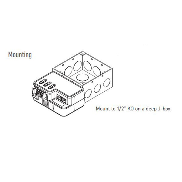
Connections shown are for example only. The next highest serial number would have load 3 and load 4 and so forth. The low voltage lmrj cables can connect to any dlm device with an open rj45 receptacle. Lmrc 221 75 c copper wire only santa clara ca 8008798585 industrial control equipment 46a9 indoor use only mounting the controller the room controller mounts to a four square deep junction box using the included mounting plate with the hinge pins extending away from the box as shown. Lmrc 220 series digital room controllers include one or two outputs to control a total of up to 20 amps. Lmrc 222 75 c copper wire only santa clara ca 8008798585 industrial control equipment 46a9 indoor use only mounting the controller the room controller mounts to a four square deep junction box using the included mounting plate with the hinge pins extending away from the box as shown.
Page 2 black wire room connected to either controller neutral of the 2 load outputs white wire load a and load b on the lmrc 222. The lmrc 211 communicates to all other dlm devices connected to the dlm local network. Terminate wiring according to wiring diagram. Load ratings include incandescent magnetic low voltage forward phase compatible electronic low voltage and led drivers neon and cold cathode and dimmable two wire and threewire fluorescent ballasts. Up to 250ma at 24vdc dlm local network characteristics when using lmrc 222. Terminate wiring according to wiring diagram.
Total load for lmrc 211 not to exceed 20a. Wiring diagrams a for the various components of the system specified including. All line voltage wiring is 12 awg. Show location of all devices including at minimum sensors load controllers and switchesdimmers for each area on reflected ceiling plans. The dimming curve must be set for proper operation. Composite wiring andor schematic diagram of each control circuit as proposed to be installed.
Gallery of Lmrc 222 Wiring Diagram