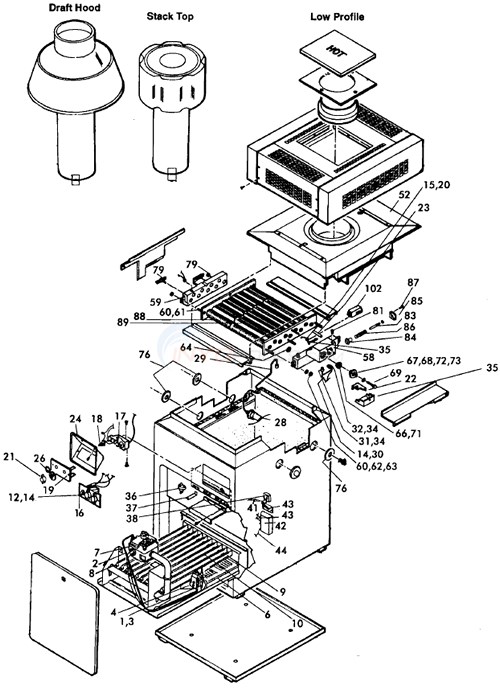
Water flow system model llg lld pool and spa heater figure 8. Install and operating manual.

Crown Boiler Wiring Diagram Auto Electrical Wiring Diagram
Laars boiler wiring diagram. Fault code identification endurance page 33 10 seconds after establishing combustion and the ignition control uses led indication to proof of flame via the flame rod signal to display the following fault codes. M4 cnc and m4 ext boiler control installation manual. Water heating systems suggested wiring diagram for tempering system water at when using the laars boiler as a source of heat changeover from heating to cooling for a combined space heatingpotable water heating system be sure to follow the instructions of the space heating system. Consult the factory or local factory. Contact teledyne laars for further information. Boilers and water heaters for residential and commercial.
Page 8 the cs 04 includes the same features as the cs 02 plus a remote tempera ture controller. Page 32 laars heating systems page 32 figure 36. Reference part numbers cs 02 and cs 04. Title category description pdf. Lld connectionschematic wiring diagram. Read this manual carefully before installation.
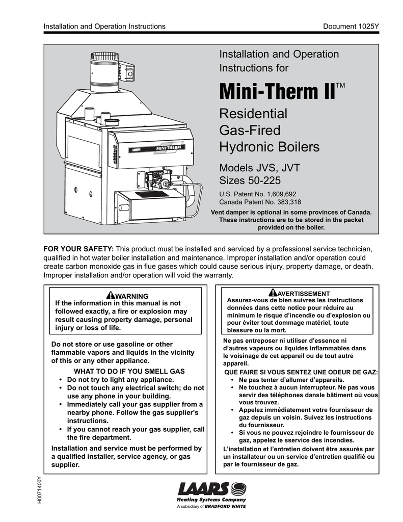
Mini combo install and operating manual. Laars heating systems mighty therm2 commerical hydronic boilers and volume water heaters including the low temp units. M4 and m4 ext boiler control installation manaual. All application and installation procedures should be reviewed completely before proceeding with the installation. Mini combo combination hydronic boiler and indirect water heater. Field wiring connections lld.
Mighty therm 500 to 1825 hydronic boiler installation manual. Ground the ignitor will be de energized.
