Ballast diagram may not necessarily take you to another two lamp ballast diagram. Control can be changed to a digital control signal dsi or dali at any time without modifying the luminaire or requiring an additional control line.

Le 8877 General Electric Refrigerator Parts Manual Look Up
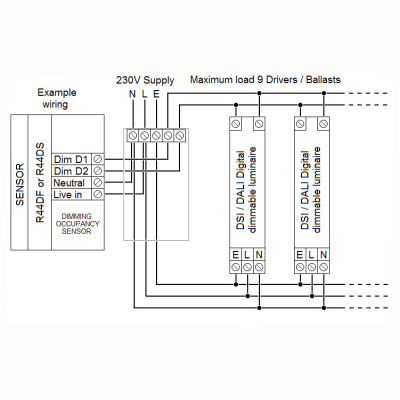
Dsi ballast wiring diagram. Connect the switch according to the wiring diagram above. It reveals the components of the circuit as streamlined forms and the power and also signal links in between the gadgets. 3 ordering data fig. 1 luminaire installation dsi smart ptm integrated 28000878 10 pcs. Assortment of fluorescent ballast wiring diagram. Mounting type article number packaging carton weight per pc.
Ballast magnetic ballast universal lighting technologies is a subsidiary of panasonic lighting americas a member of the panasonic corporation eco solutions company 2 lamp rapid start to 2 lamp electronic instant start retrofit wiring diagrams notes. Wiring diagrams and installation examples page 3 dsi smart ptm ambient light sensor and motion detector for constant light control fig. The mercury vapor ballast wiring diagram is the blueprint for the ballast circuitry including the input supply voltage and grounding methods. If you know the actual model number of the ac ballast that the emergency. Parallel ballasts can only be wired in parallel according to the diagram on the ballast. Changing the wiring on a fluorescent light fixture from series to parallel involves changing the ballast from a series to a compatible parallel ballast.
White at one end and black at the other. When the mains supply is initially connected to the pir switch it turns on the dsi and auxiliary loads for 3 minutes during its start up mode period. A ground connection must be made to all ballasts to avoid shock hazard personal injury or damage to the luminaire or installation. In case of five pole wiring it is recommended to connect the neutral conductor to d1 to prevent that 400 v are applied between adjoining terminals if a different conductor is used for the. 3 lamp series parallel ballast wiring diagramif one lamp fails or is removed in the series connected section then all lamps in that section will turn off but the lamps in the parallel circuit remain on. Per ballast or group of ballasts the cefl pirdd dsi units cannot be wired in parallel and manual dsi ballast dimming cannot be combined.
Pay close attention to the wiring diagrams and the wire colors. 2 50 21 50 193 fig. A wiring diagram is a streamlined standard pictorial representation of an electric circuit. This is applicable for 2 lamp t12 rapid start to a 2 lamp electronic t8 system. To aid in locating specific diagrams each has been bookmarked and categorized in the navigation window. 2 using the find command some diagrams feature a model list for reference.
3 lamp rapid start ballast wiring diagram 2 ballasts one 2 lamp and one 1 lamp ballast. The wiring diagram on the original light fixture ballast or transformer. 1 lamp rapid start ballast diagram. Youll notice that the line voltage hot black and neutral white 120v wires on the original ballast connect to opposite ends of the ballast.
Gallery of Dsi Ballast Wiring Diagram