Models sst120 and sst240 control modules gradually apply power to the load when energized by the control voltage. 01022019 01022019 1 comments on crydom d2425 wiring diagram.

Ox 4256 Crydom Ssr Wiring Diagram Schematic Wiring
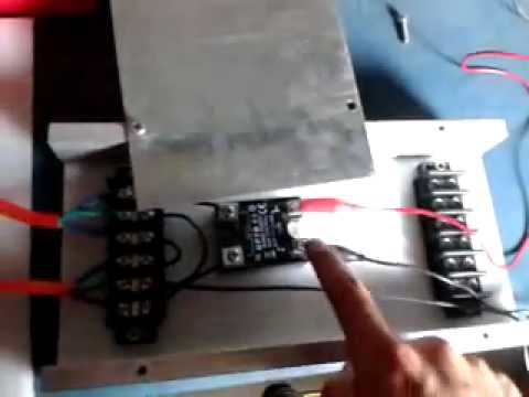
Crydom d2425 wiring diagram. Episode 1 of the crydom techlab video series shows the basic connections necessary to install a solid state relay as well as the step by step process on how to perform an operational on off test. Consult factory for sst wiring diagrams and about use with 480 vac loads. This is an scr output relay suitable for heavy industrial loads. 3 32 vdc d2410 d2425 d2450 d2475 d2490 d24110 d24125. Variety of crydom d2425 wiring diagram. Contact crydom technical support for information on the availability of a specific part number.
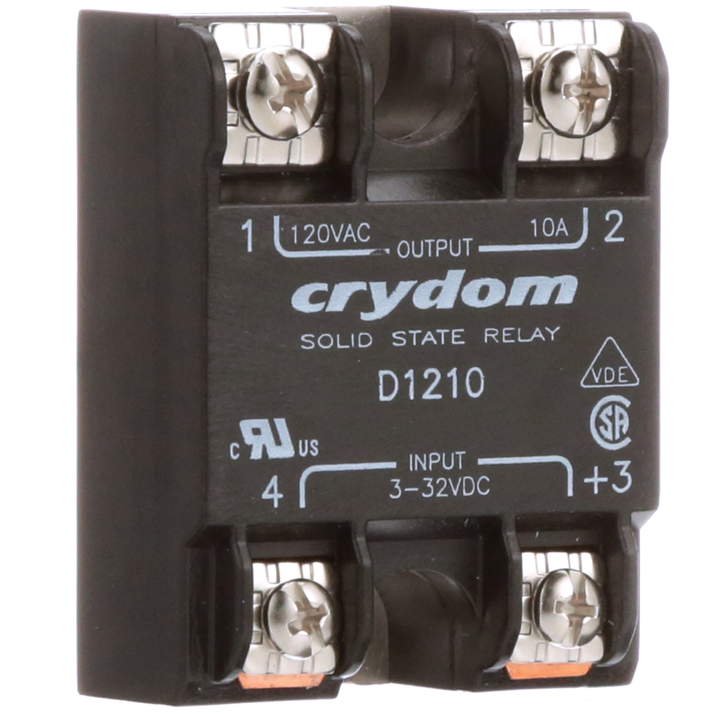
It shows the parts of the circuit as streamlined shapes as well as the power and signal links in between the gadgets. Solid state relay spst no 25 a vac panel screw zero voltage turn on. They must be used with crydom series 1 random turn on solid state relays. Assortment of crydom d2425 wiring diagram. For options only and not required for valid part number not all part number combinations are available. Crydom d2425 wiring diagram.
Wiring diagram 1 4 2 3 s oli d s tat e r ela y output input load 12 v 4. The d from crydom is a solid state relay in panel mounting. It reveals the components of the circuit as simplified shapes as well as the power and signal links between the tools. A wiring diagram is a simplified conventional pictorial representation of an electrical circuit. A wiring diagram is a streamlined standard photographic depiction of an electric circuit. For a complete set control module and solid state relay order 10sst120 25sst120.
D2425 crydom solid state relays industrial mount 25a 240vac dc datasheet inventory pricing.
Gallery of Crydom D2425 Wiring Diagram