Bulletin 1492 programmable controller wiring systems voltage v term. 1492 ifm20f f120 2 rifm20f f120 2 85132v ac 433 x 327 x 278 25 46006 192 01 235 01 221 01.
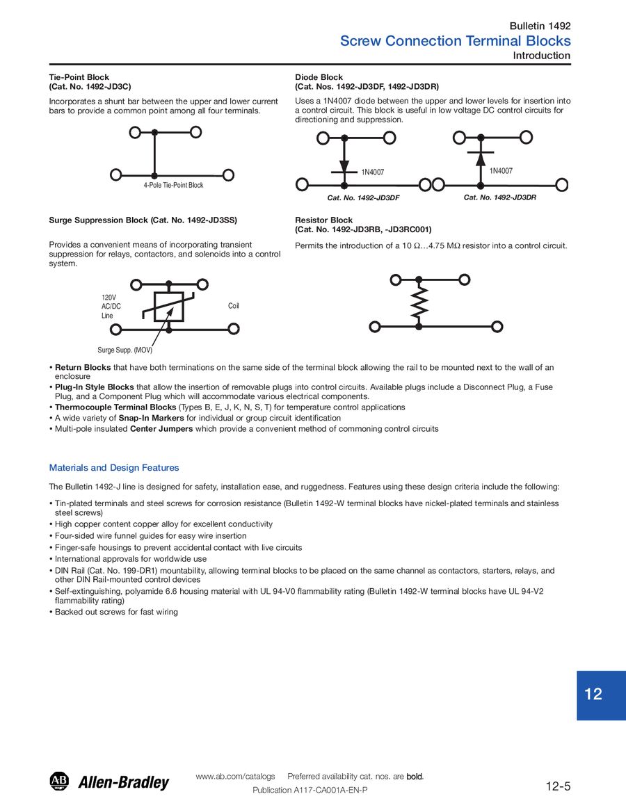
A B A C Logic Diagram F7 Wiring Diagram
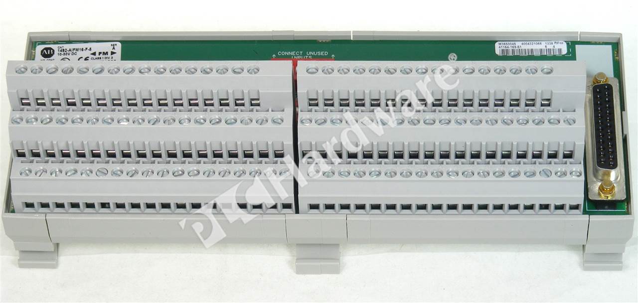
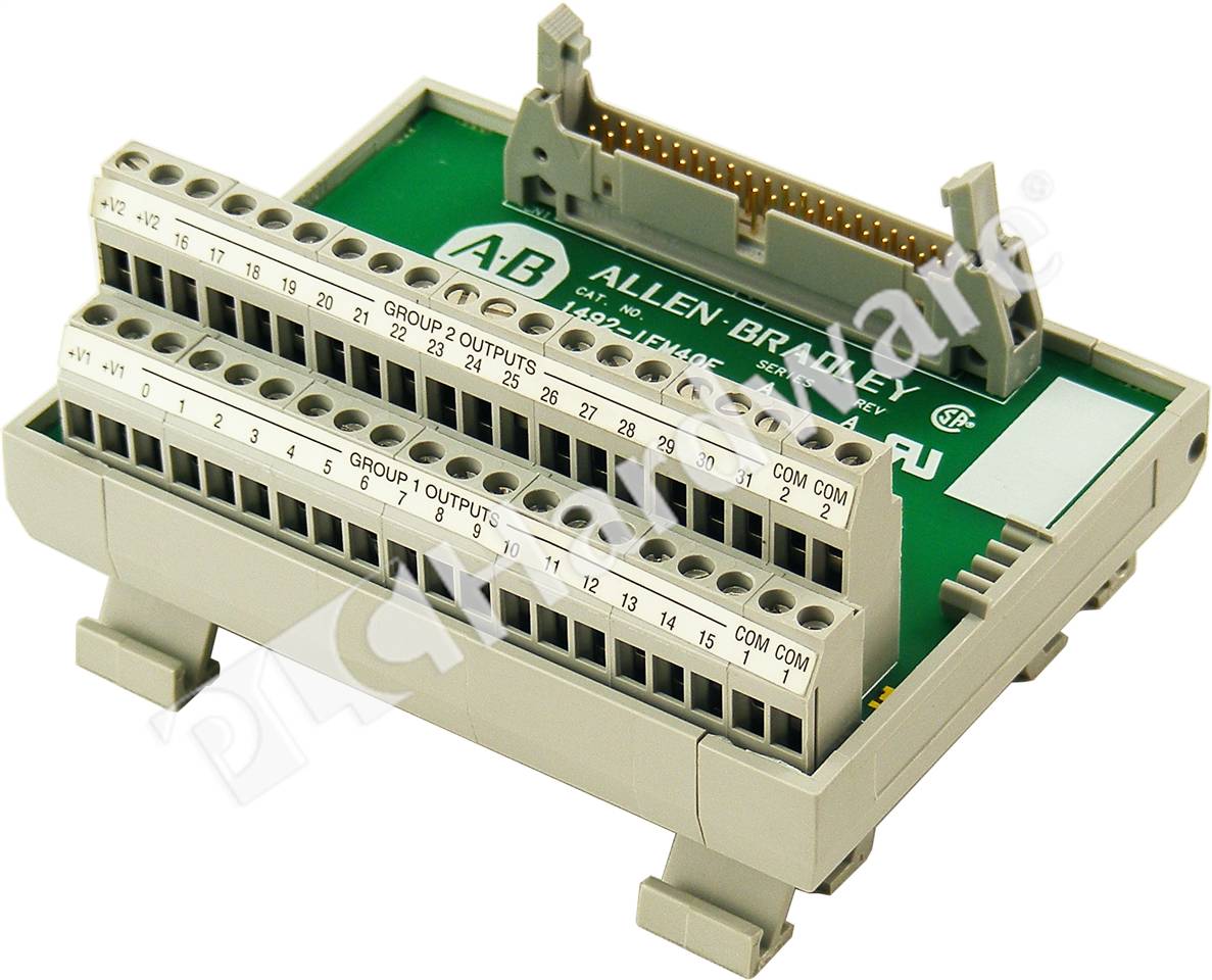
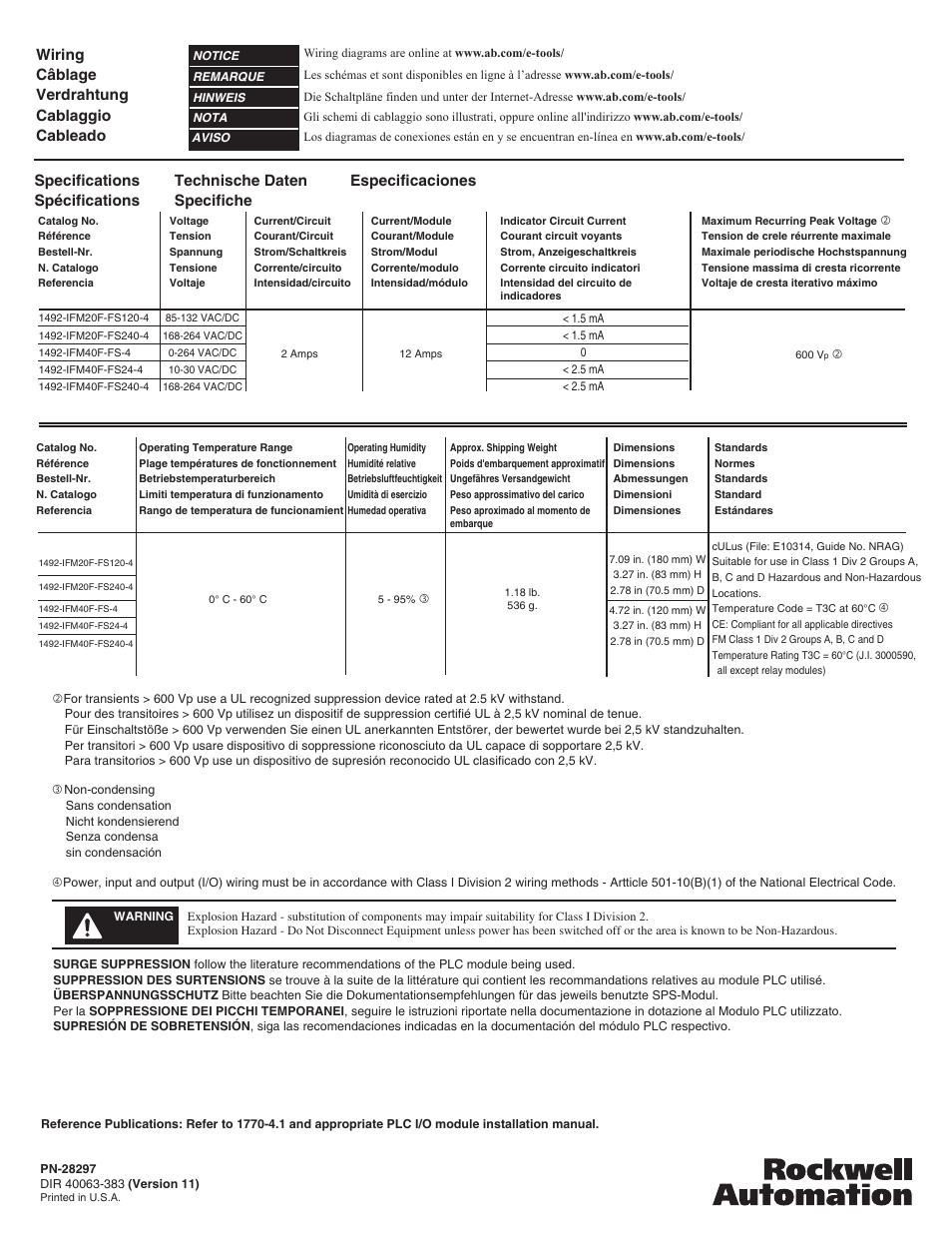
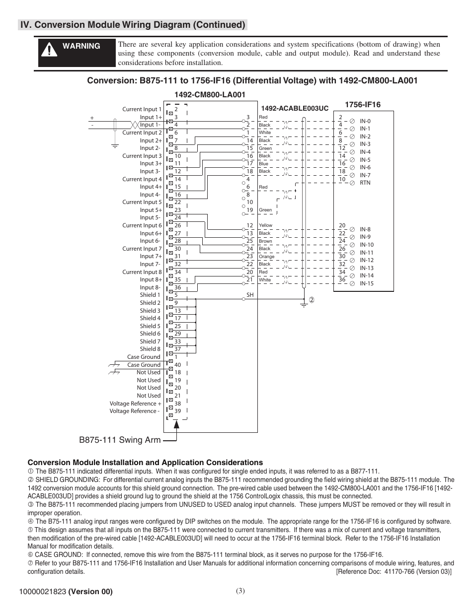
1492 ifm20f wiring diagram. Per io description fixed terminal block removable terminal block rtb plugs bulletin 1756 controllogix io module. 1492 ifm20f f24a 2 1492 rifm20f f24a 2 fusible extra terminals with 24v acdc blown fuse indicators application notes 1. Wiring refer to the label section on page 174. Compatibility to ensure proper operation with the io module do not exceed the voltage and current ratings of the ifm. 1492 wiring systems solution you simply mount the interface module ifm onto a standard din 3 rail. 1492 ifm40f fs120a 4 1492 rifm40f fs120a 4 fusible 16 individually isolated with 120v acdc blown fuse led indicators 4 terminalsinput application notes 1.
Ifm40f fs for field side wiring diagrams refer to the. Wiring refer to the label section on page 181. For field side wiring diagrams refer to the. For field side wiring diagrams refer to the wiring system web site. Per io description fixed terminal block removable. Wiring refer to the label section on page 181.
Compatibility to ensure proper operation with the io module do not exceed the voltage and current ratings of the ifm. Literature library rockwell automation. Term blown fuse led 1492 ifm20f f120 2 1492 rifm20f f120 2 1492 rtb20 m69 m69 2. Watch the following video tutorial to learn more about how the bulletin 1492 wiring system can save panel space. 1492 ifm20f f 2 1492 rifm20f f 2 fusible extra terminals for outputs application notes 1. Watch the following videos to see how our io wiring conversion systems can help you save time and money and reduce wiring errors when converting from plc 5 io to controllogix io.
Compatibility to ensure proper operation with the io module do not exceed the voltage and current ratings of the ifm. 12122018 12122018 4 comments on wiring diagram 1492 ifm40f fs120 2 september digitalanalog programmable controller wiring systems. 1492 ifm20f f 2 1492 rifm20f f 2 fusible extra terminals for outputs application notes 1. Wiring refer to the label section on page 181. Bulletin 1492 programmable controller wiring systems voltage v term. For field side wiring diagrams refer to the wiring system web site.
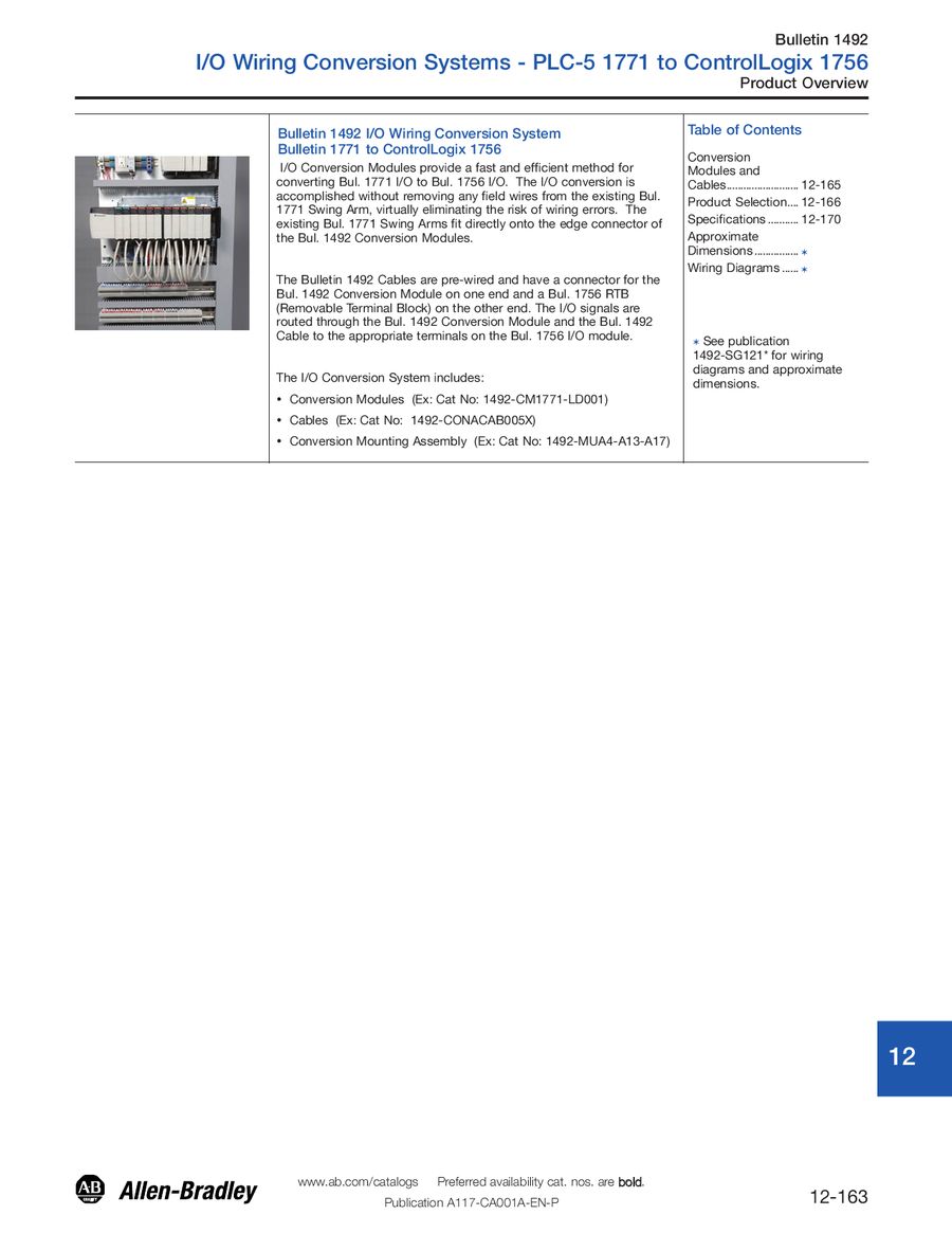
Compatibility to ensure proper operation with the io module do not exceed the voltage and current ratings of the ifm. Then attach the 1492 cable with its pre wired programmable controller removable terminal block to the programmable controller io module and plug the connector into the ifm. 1492 ifm20f f 2 1492 rifm20f f 2 1492 rtb20 m69 e69 e69 m69 120 2 extr.
Gallery of 1492 Ifm20f Wiring Diagram